[Direct Rec Function]
OFF: Normally set at this position.
ON: This settingenables Direct Rec.
AV1 Input(A1) becomes exclusive channel for Direct Rec.
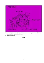
3. Perform the PG SHIFTER ADJUSTMENT.
(Refer to the Electrical Adjustment Procedures.)
Note:
1. It should be performed before tuning.
2. Do not cut off the power source during reset.
Fig. S1
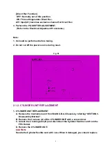
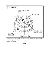
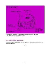
2.1.2. CYLINDER UNIT REPLACEMENT
1. CYLINDER UNIT REPLACEMENT
A. Remove the mechanism unit from MAIN C.B.A./Chassis by referring“SECTION 3.
Disassembly Method”.
B. Remove the 3 screws (A) of the CYLINDER UNIT with a screw driver.
C. Unlock the 4 locking tabs (B) and disconnect the Cylinder fiexible card from the
FPC Holder.
D. Remove the CYLINDER UNIT.
CAUTION:
Handle the Cylinder flexible card with care. When it damaged, you should replace
4
Summary of Contents for NV-FJ600A
Page 6: ...6 ...
Page 16: ...3 1 2 DETAIL OF DISASSEMBLY METHOD 1 REMOVAL OF THE TOP PANEL Remove 2 Screws A Fig D2 16 ...
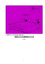
Page 17: ...2 REMOVAL OF THE FRONT PANEL UNIT Unlock 6 Tabs B Fig D3 17 ...
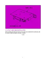
Page 19: ...4 REMOVAL OF THE MAIN C B A Remove 4 Screws F Unlock 6 Tabs G Fig D5 19 ...
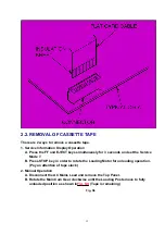
Page 20: ...5 SERVICING POSITION Fig D6 20 ...
Page 32: ...C3012 VCEA0JCB221 E CAPACITOR 6 3V 220U 1 32 ...
Page 34: ...C4029 VCEA0JCB220 E CAPACITOR 6 3V 22U 1 34 ...
Page 36: ...C7305 ECUM1H123KBN C CAPACITOR CH 50V 0 012U 1 36 ...
Page 38: ...D2003 1SS254 DIODE 1 38 ...
Page 43: ...R3050 ERJ6GMYJ104 M RESISTOR CH 1 10W 100K 1 43 ...
Page 45: ...R4522 ERJ6RBD393 M RESISTOR CH 1 10W 39K 1 45 ...
Page 47: ...R7506 ERJ6GMYJ123 M RESISTOR CH 1 10W 12K 1 47 ...
Page 50: ...C2003 VCEA0JCB220 E CAPACITOR 6 3V 22U 1 50 ...
Page 52: ...C3045 VCEA0JCB101 E CAPACITOR 6 3V 100U 1 52 ...
Page 54: ...C4513 VCEA1HCBR22 E CAPACITOR 50V 0 22U 1 54 ...
Page 61: ...R4007 ERJ6GMZ0R00 M RESISTOR CH 1 10W 0 1 61 ...
Page 63: ...R6008 ERJ6GMYJ334 M RESISTOR CH 1 10W 330K 1 63 ...


