3. UPPER CYLINDER ASSEMBLY
When reassembling, perform the steps in the reverse order.
Notes:
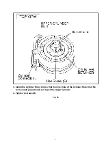
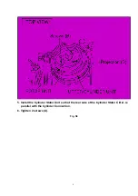
1. Install the Cylinder Retainer so that the 2 holes on top of the Cylinder Retainer are
at right angles with the Cylinder Connection.
2. Tighten the Hex screw (C) (1.5 mm) while pressing down on top of the Cylinder
Retainer.
Fig. S4
7
Summary of Contents for NV-FJ600A
Page 6: ...6 ...
Page 16: ...3 1 2 DETAIL OF DISASSEMBLY METHOD 1 REMOVAL OF THE TOP PANEL Remove 2 Screws A Fig D2 16 ...
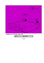
Page 17: ...2 REMOVAL OF THE FRONT PANEL UNIT Unlock 6 Tabs B Fig D3 17 ...
Page 19: ...4 REMOVAL OF THE MAIN C B A Remove 4 Screws F Unlock 6 Tabs G Fig D5 19 ...
Page 20: ...5 SERVICING POSITION Fig D6 20 ...
Page 32: ...C3012 VCEA0JCB221 E CAPACITOR 6 3V 220U 1 32 ...
Page 34: ...C4029 VCEA0JCB220 E CAPACITOR 6 3V 22U 1 34 ...
Page 36: ...C7305 ECUM1H123KBN C CAPACITOR CH 50V 0 012U 1 36 ...
Page 38: ...D2003 1SS254 DIODE 1 38 ...
Page 43: ...R3050 ERJ6GMYJ104 M RESISTOR CH 1 10W 100K 1 43 ...
Page 45: ...R4522 ERJ6RBD393 M RESISTOR CH 1 10W 39K 1 45 ...
Page 47: ...R7506 ERJ6GMYJ123 M RESISTOR CH 1 10W 12K 1 47 ...
Page 50: ...C2003 VCEA0JCB220 E CAPACITOR 6 3V 22U 1 50 ...
Page 52: ...C3045 VCEA0JCB101 E CAPACITOR 6 3V 100U 1 52 ...
Page 54: ...C4513 VCEA1HCBR22 E CAPACITOR 50V 0 22U 1 54 ...
Page 61: ...R4007 ERJ6GMZ0R00 M RESISTOR CH 1 10W 0 1 61 ...
Page 63: ...R6008 ERJ6GMYJ334 M RESISTOR CH 1 10W 330K 1 63 ...


