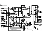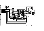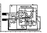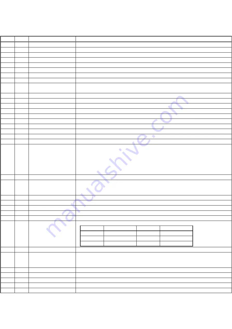
Function
Power failure detection input.
This port supplies low during SP mode.
Supply reel pulse input.
Take-up reel pulse input.
Remote Controller pulse input.
OSD REC control output.
OSD REC control output.
Hi-Fi audio mute control output.
EE:Low
VV:High
FIP driver chip selection.
This port is high during S-VHS playback mode.
VTR/TV mode switching control.
Channel switching control.
FIP driver serial clock output.
FIP driver serial data input.
FIP driver serial data output.
IIC serial data in/output
IIC serial clock output
Not used
Capstan torque switching control.
1. FF/REW Mode
Capstan rotation speed is 1300 rpm or more without VHS-C cassette:High
Capstan rotation speed is less than 1300 rpm without VHS-C cassette:High impedance
VHS-C cassette:High imedance
2. Except FF/REW Mode:High impedance
Capstan motor current limitter output.
Capstan rotation direction control.
Reverse : High
Forward : Low
Video head switching signal output.
This port supplies artificial vertical sync signal to stabilize the picture in special playback mode.
This port is low during reset.
Audio signal recording on/off control.
Video signal recording on/off control.
This port supplies high during a certain time from starting the recording.
NTSC 2H
PAL 3H
NTSC 4H
---
NTSC 6H
PAL 6H
Oscillator output for main clock adjustment.
Full erase on/off control.
ON:Low
OFF:High
Audio signal recording on/off control.
Audio head switching signal output.
Capstan torque control.
Cylinder torque control.
Not used
OSD REC1
9 sec
18 sec
---
Pin No.
1
28
O
11
12
13
14
15
16
CUR. EMPH(H)
REC MODE
OUTPUT TIMING
17
23
25
22
18
19
REC MODE
6 sec
12 sec
18 sec
OUTPUT TIMING
4
5
2
3
6
7
8
9
10
21
24
31
32
33
26
27
29
34
35
S.REEL.PULSE
30
128Hz
FULL ERASE(L)
O
20
VTR(H)/TV(L)
O
T.REEL.PULSE
I.R.
In/Out
I
O
P.FAIL.IN(L)
Port Name
SP(L)
OSD REC1
FM MUTE(H)
VIDEO EE(H)
FL DRV CS(L)
SQ PB(H)
IIC.TALK/LSN
IIC.CLK
CH H/L
IC.CLK
IC.LSN
IC.TLK
N.C.
HALF WAVE(H)
CURRENT LIMIT
CAP R/F
VIDEO H.SW
ART V/H/N
RESET(L)
D.A.REC(H)
D.REC(H)
BIAS(L)
A H SW
CAP ET
CYL ET
N.C.
I
I
I
O
O
O
I
I
O
I
O
O
O
O
O
O
O
O
O
I
O
O
O
O
O
O
O
O
O
O
Summary of Contents for NV-FJ600A
Page 6: ...6 ...
Page 16: ...3 1 2 DETAIL OF DISASSEMBLY METHOD 1 REMOVAL OF THE TOP PANEL Remove 2 Screws A Fig D2 16 ...
Page 17: ...2 REMOVAL OF THE FRONT PANEL UNIT Unlock 6 Tabs B Fig D3 17 ...
Page 19: ...4 REMOVAL OF THE MAIN C B A Remove 4 Screws F Unlock 6 Tabs G Fig D5 19 ...
Page 20: ...5 SERVICING POSITION Fig D6 20 ...
Page 32: ...C3012 VCEA0JCB221 E CAPACITOR 6 3V 220U 1 32 ...
Page 34: ...C4029 VCEA0JCB220 E CAPACITOR 6 3V 22U 1 34 ...
Page 36: ...C7305 ECUM1H123KBN C CAPACITOR CH 50V 0 012U 1 36 ...
Page 38: ...D2003 1SS254 DIODE 1 38 ...
Page 43: ...R3050 ERJ6GMYJ104 M RESISTOR CH 1 10W 100K 1 43 ...
Page 45: ...R4522 ERJ6RBD393 M RESISTOR CH 1 10W 39K 1 45 ...
Page 47: ...R7506 ERJ6GMYJ123 M RESISTOR CH 1 10W 12K 1 47 ...
Page 50: ...C2003 VCEA0JCB220 E CAPACITOR 6 3V 22U 1 50 ...
Page 52: ...C3045 VCEA0JCB101 E CAPACITOR 6 3V 100U 1 52 ...
Page 54: ...C4513 VCEA1HCBR22 E CAPACITOR 50V 0 22U 1 54 ...
Page 61: ...R4007 ERJ6GMZ0R00 M RESISTOR CH 1 10W 0 1 61 ...
Page 63: ...R6008 ERJ6GMYJ334 M RESISTOR CH 1 10W 330K 1 63 ...

