http://cxema.ru
3. ADJUSTMENT PROCEDURES
3.1. DISASSEMBLY METHOD
3.1.1. DISASSEMBLY FLOW CHART
This flow chart indicates disassembly steps of the cabinet parts and the circuit boards in order to find the
necessary items for servicing.
When reassembling, perform the steps in the reverse order.
Fig. D1
3.1.2. DETAIL OF DISASSEMBLY METHOD
1. REMOVAL OF THE TOP PANEL
Remove
4 Screws (A)
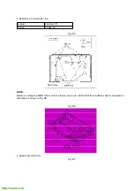
Fig.D2
2. REMOVAL OF THE FRONT PANEL UNIT
Summary of Contents for NV-FJ620EG
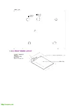
Page 18: ...http cxema ru 3 3 8 CIRCUIT BOARD LAYOUT ...
Page 59: ...http cxema ru 10 2 CASING PARTS SECTION ...
Page 60: ...http cxema ru 10 3 PACKING PARTS SECTION ...
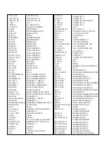
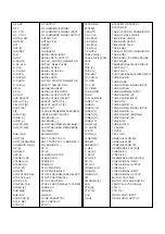
Page 61: ...http cxema ru 11 REPLACEMENT PARTS LIST 11 1 CHASSIS PARTS SECTION PARTS LIST ...
Page 68: ...http cxema ru ...
Page 70: ...http cxema ru ...
Page 72: ...http cxema ru ...
Page 74: ...http cxema ru ...
Page 80: ...http cxema ru ...
Page 82: ...http cxema ru ...
Page 84: ...http cxema ru ...
Page 86: ...http cxema ru ...
Page 88: ...http cxema ru ...
Page 90: ...http cxema ru ...
Page 93: ......
Page 94: ......
Page 95: ......
Page 96: ......
Page 97: ......
Page 98: ......
Page 99: ......
Page 100: ......
Page 101: ......
Page 102: ......


