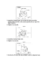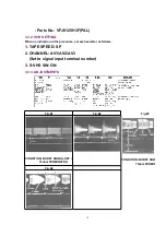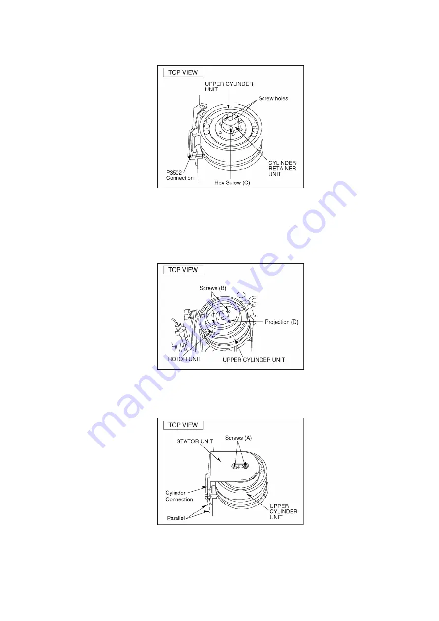
3. Install the Cylinder Rotor Unit so that the inner hole of the
Cylinder Rotor Unit fits to the small projection (D) on top of the
Upper Cylinder.
4. Tighten 2 screws (B).
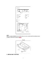
Fig. S6
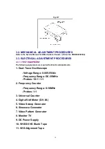
5. install the Cylinder Stator Unit.
6. Tighten 2 screws (A).
Fig. S7
7. Confirm the PG SHIFTER ADJUSTMENT with the alignment tape
8
Summary of Contents for NV-HS880EG
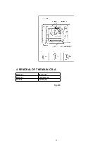
Page 16: ...4 REMOVAL OF THE MAIN C B A Remove Screw F Remove 4 Screws G Unlock 2 Tabs H Fig D5 16 ...
Page 23: ...3 3 8 CIRCUIT BOARD LAYOUT 23 ...
Page 26: ...10 2 CASING PARTS SECTION 26 ...
Page 27: ...10 3 PACKING PARTS SECTION 27 ...
Page 28: ...11 REPLACEMENT PARTS LIST 11 1 CHASSIS PARTS SECTION PARTS LIST 28 ...
Page 41: ...D7501 MAZ4220NMF DIODE MAVD 41 ...
Page 43: ...K7301 ERJ6GEY0R00V M RESISTOR CH 1 10W 0 D0GBR00JA017 43 ...
Page 46: ...Q1104 2SD1992A R TRANSISTOR 46 ...
Page 48: ...R0715 ERJ3GEYJ223 M RESISTOR CH 1 16W 22K 48 ...


