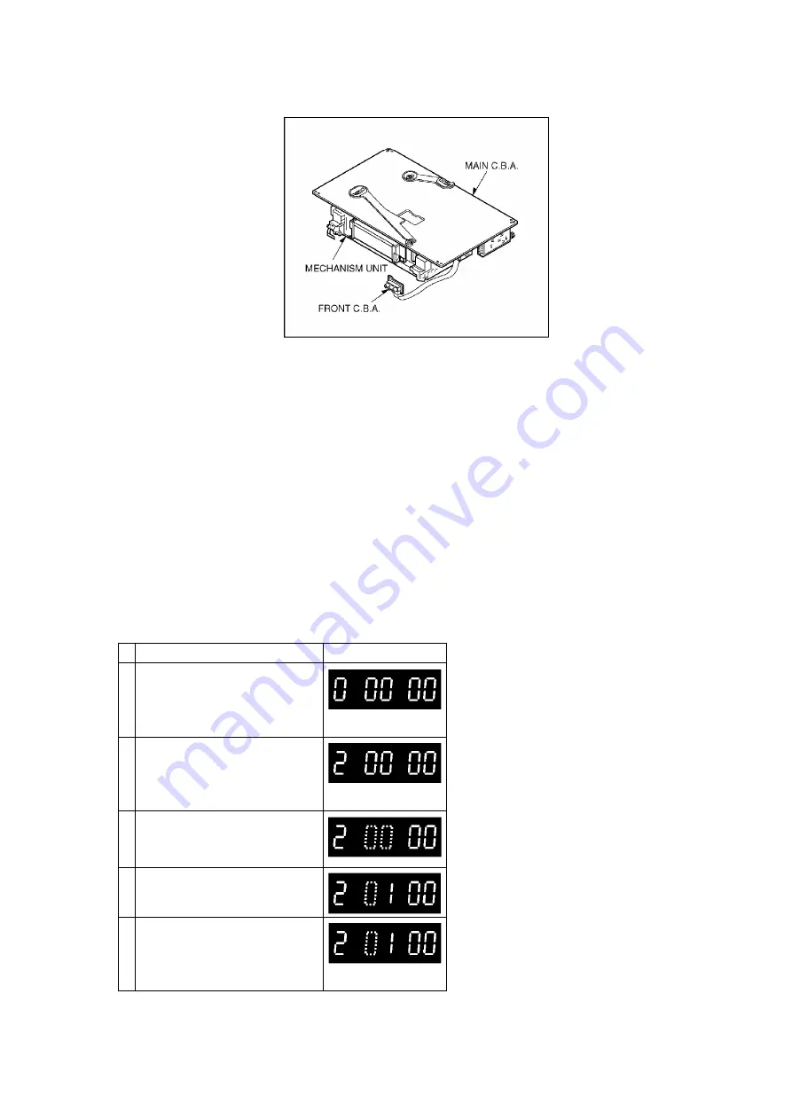
3.2. MECHANICAL ADJUSTMENT PROCEDURES
Refer to the Service Manual for R4-Mechanism Chassis.
(Order No. VRD0202010C8)
3.3. ELECTRICAL ADJUSTMENT PROCEDURES
This section provides complete adjustment procedures required for electric circuits of VCR.
3.3.1. TEST EQUIPMENT
To perform electrical adjustments following equipment is required.
1. VHS Alignment Tape. (VFJ8125H3F)
2. Monitor
3.3.2. SERVO SECTION
PG SHIFTER ADJUSTMENT
PROCEDURE
F.I.P. DISPLAY
1. Turn on the Service Mode
1.Press the FF key and the
EJECT key simultaneously
for more than 3 seconds.
2. Activate the Service Mode 2
While keep pressing FF key,
press the EJECT key in
twice.
3. Activate the Entering Mode.
Press the EJECT key for
more than 3 seconds.
4. Set the Mode 2.
Press the CH UP key once.
5. Insert the alignment
cassette tape (VFJ8125H3F)
The PG Shifter Adjustment
starts automatically.
25
Summary of Contents for NV-HV61EE
Page 21: ...2 REMOVAL OF THE BACK PANEL Remove 2 Screws C Remove Screw D Unlock 4 Tabs E Fig D3 21 ...
Page 29: ...10 2 CASING PARTS SECTION 29 ...
Page 30: ...10 3 PACKING PARTS SECTION 30 ...
Page 31: ...11 REPLACEMENT PARTS LIST 31 ...
Page 41: ...C4537 ECJ2VC1H560G CHIP CAPACITOR 41 ...
Page 44: ...D2002 B0AAED000003 DIODE 44 ...
Page 47: ...Q1152 2SC3311ASA TRANSISTOR 47 ...
Page 49: ...R1502 ERJ3GEYJ273V CHIP RESISTOR 49 ...
Page 54: ...W519 ERJ3GEY0R00V CHIP JUMPER 54 ...
Page 109: ...4 1 3 PARTS NAME OF R4 MECHANISM Fig M2 ...
Page 139: ...34 ...


