53
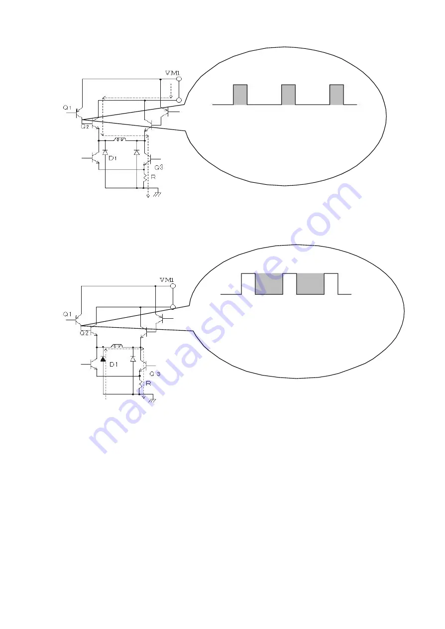
PWM Input [
In the positive period]
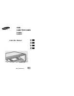
PWM Input [In the negative period]
(Motor Power)
The motor current in positive period of PWM drive is
flows as follows.
VM1
→
Q2
→
L
→
Q3
→
R
PWM Input Wave
form
at Q2-b
(Motor Power)
The motor current in negative period of PWM drive
is flows as follows by the reverse electromotive force.
D1
→
L
→
Q3
→
R
PWM Input Wave
form
at Q2-b
L
×
2
L
×
2
Summary of Contents for NV-HV61GN
Page 21: ...2 REMOVAL OF THE BACK PANEL Remove 2 Screws C Remove Screw D Unlock 4 Tabs E Fig D3 21 ...
Page 29: ...10 2 CASING PARTS SECTION 29 ...
Page 30: ...10 3 PACKING PARTS SECTION 30 ...
Page 31: ...11 REPLACEMENT PARTS LIST 31 ...
Page 41: ...C4537 ECJ2VC1H560G CHIP CAPACITOR 41 ...
Page 44: ...D2002 B0AAED000003 DIODE 44 ...
Page 47: ...Q1152 2SC3311ASA TRANSISTOR 47 ...
Page 49: ...R1502 ERJ3GEYJ273V CHIP RESISTOR 49 ...
Page 54: ...W519 ERJ3GEY0R00V CHIP JUMPER 54 ...
Page 109: ...4 1 3 PARTS NAME OF R4 MECHANISM Fig M2 ...
Page 139: ...34 ...


