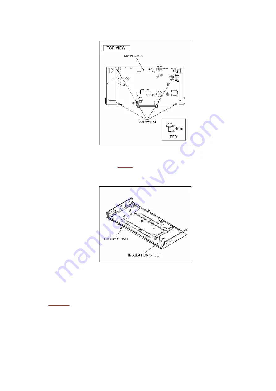
NOTE:
Before mounting the MAIN C.B.A. onto the frame, be sure to confirm that the insulation sheet is
mounted on the frame as shown in
Fig. D8
.
Fig. D8
7. SERVICING POSITION
Install the Mechanism Unit on to the MAIN C.B.A..
Then fix a screw (I), and connect two frexible card Connectors
(Cylinder connector, AC Head connector) and P1531 as shown in
Fig. D6
.
Fig. D9
24
Summary of Contents for NV-HV61GN
Page 21: ...2 REMOVAL OF THE BACK PANEL Remove 2 Screws C Remove Screw D Unlock 4 Tabs E Fig D3 21 ...
Page 29: ...10 2 CASING PARTS SECTION 29 ...
Page 30: ...10 3 PACKING PARTS SECTION 30 ...
Page 31: ...11 REPLACEMENT PARTS LIST 31 ...
Page 41: ...C4537 ECJ2VC1H560G CHIP CAPACITOR 41 ...
Page 44: ...D2002 B0AAED000003 DIODE 44 ...
Page 47: ...Q1152 2SC3311ASA TRANSISTOR 47 ...
Page 49: ...R1502 ERJ3GEYJ273V CHIP RESISTOR 49 ...
Page 54: ...W519 ERJ3GEY0R00V CHIP JUMPER 54 ...
Page 109: ...4 1 3 PARTS NAME OF R4 MECHANISM Fig M2 ...
Page 139: ...34 ...


