SERVICE NOTES.
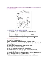
5.2.5. Capstan Belt, Support Angle, Intermediate Gear B, and Main Cam Gear
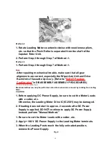
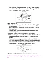
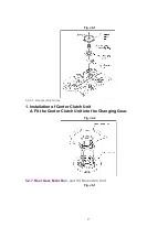
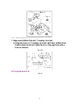
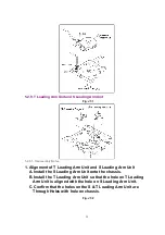
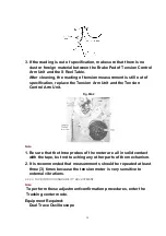
Fig. J3-1
5.2.5.1. Reassembly Notes
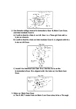
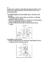
1. Alignment of Main Cam Gear, Drive Rack Arm, and Main Rod
A. Confirm that the hole on Main Rod is a Through Hole with a
hole on chassis.
B. Confirm that the hole on Drive Rack Arm is a Through Hole with
a hole on chassis.
C. Install the Main Cam Gear so that the projection of Main Cam
Gear is in the upward position as shown.
Fig. J3-2
24
Summary of Contents for NV-SJ4130PN
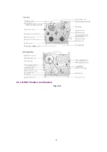
Page 6: ...Fig 1 4 Fig 1 5 6 ...
Page 22: ...5 2 3 EJECT Position Confirmation Fig J1 2 22 ...
Page 48: ...10 2 MECHANISM BOTTOM SECTION 48 ...
Page 49: ...10 3 CASSETTE UP COMPARTMENT SECTION 49 ...
Page 50: ...10 4 CHASSIS FRAME AND CASING PARTS SECTION 50 ...
Page 51: ...10 5 PACKING PARTS AND ACCESSORIES SECTION 51 ...
Page 56: ...11 2 MECHANICAL REPLACEMENT PARTS LIST MECHANICAL REPLACEMENT PARTS 56 ...
Page 96: ......
Page 97: ......

