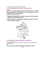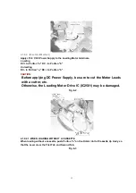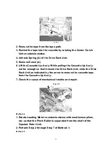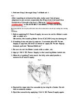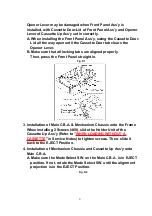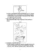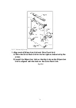
B. Install the Mechanism Chassis and Cassette Up Ass’y straight
onto the Main C.B.A. so that the Sensor LED clears the hole in
the Mechanism Chassis and that 2 Connectors (P4001, P6201)
are aligned and seated securely.
5. Connection of Mechanism Chassis
Connect the Flat Cables. Then, install the A/C Shield Plate as
shown.
Fig. D3
6. Installation of Cassette Up Ass’y
A. Confirm that the Locking Tab under the Cassette Up Ass’y is in
Hole on the Mechanism Chassis when installing the Cassette
Up Ass’y. Then, slide the Cassette Up Ass’y towards the back.
22
Summary of Contents for NV-SJ4140PN
Page 6: ...Fig 1 4 Fig 1 5 6 ...
Page 19: ...Figure 19 ...
Page 24: ...5 2 3 EJECT Position Confirmation Fig J1 2 24 ...
Page 35: ...5 3 CASSETTE UP ASSEMBLY SECTION 5 3 1 Top Plate Wiper Arm Unit and Holder Unit Fig K1 1 35 ...
Page 50: ...10 2 MECHANISM BOTTOM SECTION 50 ...
Page 51: ...10 3 CASSETTE UP COMPARTMENT SECTION 51 ...
Page 52: ...10 4 CHASSIS FRAME AND CASING PARTS SECTION 52 ...
Page 53: ...10 5 PACKING PARTS AND ACCESSORIES SECTION 53 ...

