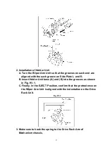
2. Installation of Holder Unit
A. Turn the Wiper Arm Unit so that the grooves on each end are
aligned with the each groove on Side Plate L and R.
B. Insert Holder Unit boss (A) and (B) into the grooves as shown
in Fig. K1-1.
C. Finally, in the EJECT Position, confirm that the protrudence on
the Wiper Arm Unit is aligned with the indentation on the Drive
Rack Unit.
Fig. K1-3
3. Make sure to hook the spring to the Drive Rack Arm of
Mechanism chassis.
37
Summary of Contents for NV-SJ4140PN
Page 6: ...Fig 1 4 Fig 1 5 6 ...
Page 19: ...Figure 19 ...
Page 24: ...5 2 3 EJECT Position Confirmation Fig J1 2 24 ...
Page 35: ...5 3 CASSETTE UP ASSEMBLY SECTION 5 3 1 Top Plate Wiper Arm Unit and Holder Unit Fig K1 1 35 ...
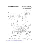
Page 50: ...10 2 MECHANISM BOTTOM SECTION 50 ...
Page 51: ...10 3 CASSETTE UP COMPARTMENT SECTION 51 ...
Page 52: ...10 4 CHASSIS FRAME AND CASING PARTS SECTION 52 ...
Page 53: ...10 5 PACKING PARTS AND ACCESSORIES SECTION 53 ...


