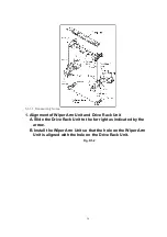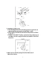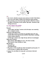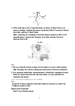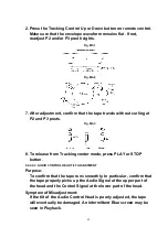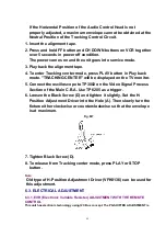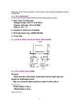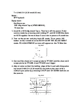
VHS Alignment Tape (VFMS0003H6)
Post Adjustment Driver (VFK0329)
H-Position Adjustment Driver (VFK0330)
6.2.2.2.1. ENVELOPE OUTPUT ADJUSTMENT
The height of the P2 and P3 Posts replacement part is preadjust at the factory.
Purpose:
To achieve a satisfactory picture and secure precise tracking.
Symptom of Misadjustment:
If the envelope is output poorly, much noise will appear in the
picture. Then the tracking will lose precision and the playback
picture will be distorted by any slight variation of the tracking
control circuit.
Equipment Required:
Post Adjustment Driver (VFK0329)
1. Insert the alignment tape.
2. Press and hold FF button and CH DOWN buttons on VCR together
over 5 seconds in power off condition.
The power comes on and the unit goes into service mode.
3. Play back the alignment tape.
4. To enter Tracking center mode, press PLAY button in Play back
mode. "TRACKING CENTER" will be displayed on the TV monitor.
5. Connect the oscilloscope to TP3002 on the Video Signal Process
Section of the Main C.B.A. Use TP6205 as a trigger.
6. Confirm that the RF envelope is flat enough (V1/V-max. is 0.7 or
more). If not, with Post Adjustment Driver, adjust P2 and P3 post
height so that the envelope waveform becomes as flat (V1/V-max.
is 0.7 or more) as possible (No envelope drop). If the envelope
drop appears on the left-half of the waveform, adjust P2 post
height. If the envelope drop appears on the right-half of the
waveform, adjust P3 post height.
CAUTION:
Overtightening P2 and P3 posts may cause the threads to strip.
Note:
It will be possible to confirm Step 6 according to following steps.
1. Release the Tracking center mode.
41
Summary of Contents for NV-SJ4140PN
Page 6: ...Fig 1 4 Fig 1 5 6 ...
Page 19: ...Figure 19 ...
Page 24: ...5 2 3 EJECT Position Confirmation Fig J1 2 24 ...
Page 35: ...5 3 CASSETTE UP ASSEMBLY SECTION 5 3 1 Top Plate Wiper Arm Unit and Holder Unit Fig K1 1 35 ...
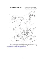
Page 50: ...10 2 MECHANISM BOTTOM SECTION 50 ...
Page 51: ...10 3 CASSETTE UP COMPARTMENT SECTION 51 ...
Page 52: ...10 4 CHASSIS FRAME AND CASING PARTS SECTION 52 ...
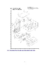
Page 53: ...10 5 PACKING PARTS AND ACCESSORIES SECTION 53 ...


