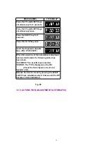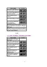
PROCEDURES
FIP DISPLAY
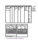
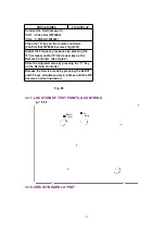
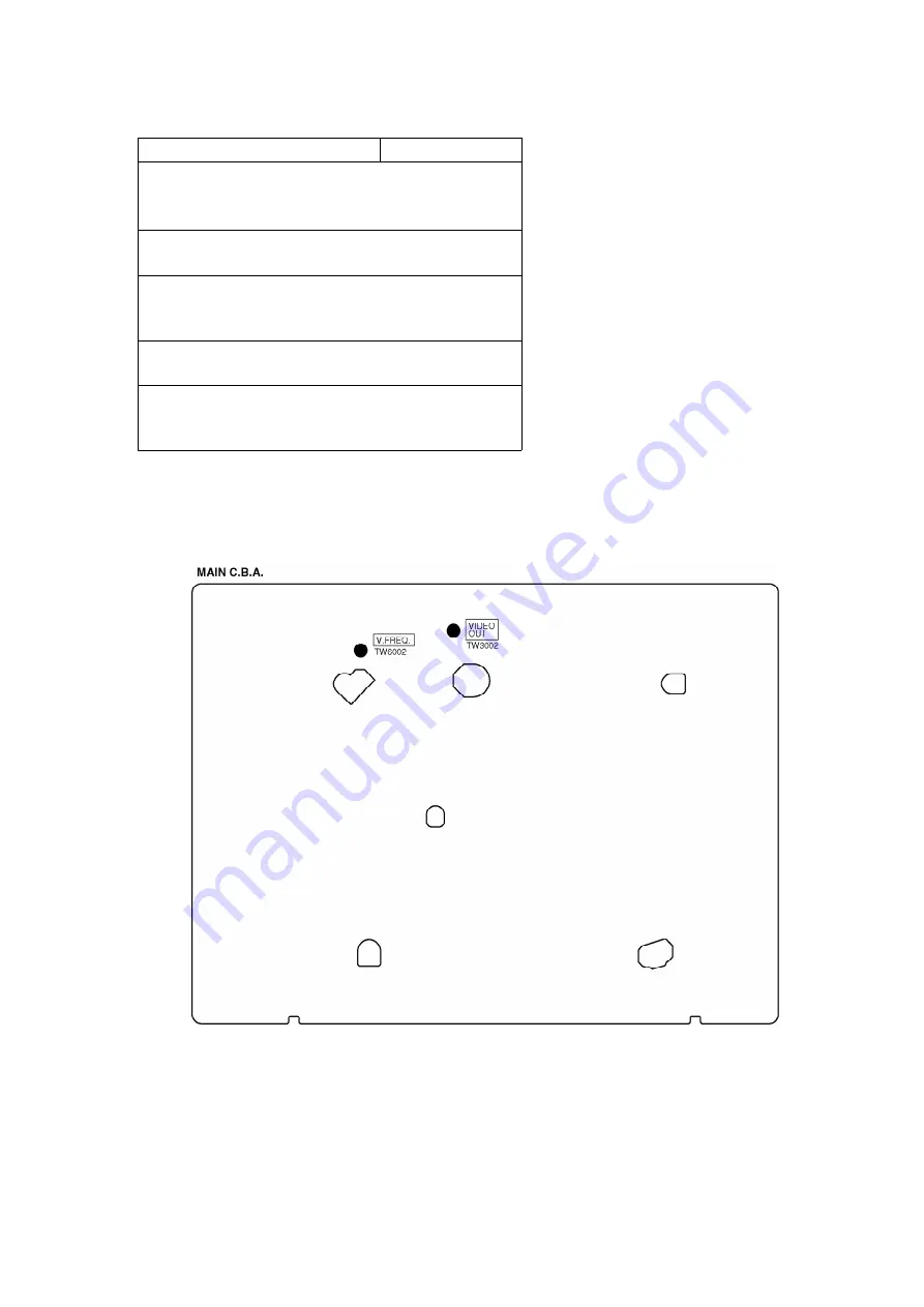
Connect the Oscilloscope to:
*CH1....Video Out (TW3002).
*CH2....V.FREQ.(TW6002)
Press the "4" key on the remote controller.
(Confirm that TW6002 becomes high(5V)).
Adjust the Frequency response by pressing the
"2"(increase) and/or "8"(decrease) key on the
Remote Controller. (See Fig.E2)
Store the Adjusted value by pressing the "5" key
on the Remote Controller.
Release the Service mode by pressing the EJECT
and FF keys simultaneously in 6 times until the FIP
becomes normal indication.
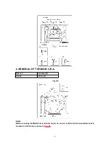
Fig. E5
3.3.7. LOCATION OF TEST POINTS & CONTROLS
3.3.8. CIRCUIT BOARD LAYOUT
21
Summary of Contents for NV-SJ420EG
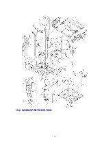
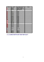
Page 24: ...10 2 CASING PARTS SECTION 24 ...
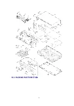
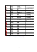
Page 25: ...10 3 PACKING PARTS SECTION 25 ...
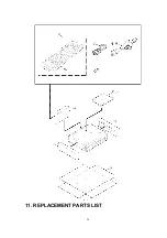
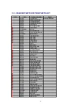
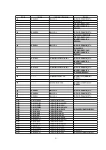
Page 26: ...11 REPLACEMENT PARTS LIST 26 ...
Page 80: ......
Page 81: ......
Page 82: ......
Page 83: ......
Page 84: ......
Page 85: ......
Page 86: ......
Page 87: ......
Page 88: ......
Page 89: ......
Page 90: ......
Page 91: ......
Page 92: ......
Page 93: ......
Page 94: ......
Page 95: ......
Page 96: ......
Page 97: ......
Page 98: ......
Page 99: ......
Page 100: ......
Page 101: ......
Page 102: ......
Page 103: ......
Page 104: ......
Page 105: ......
Page 106: ......
Page 107: ......
Page 108: ......
Page 109: ......
Page 110: ......
Page 111: ......
Page 112: ......
Page 113: ......
Page 114: ......
Page 115: ......
Page 116: ......
Page 117: ......
Page 118: ......
Page 119: ......
Page 120: ......
Page 121: ......
Page 122: ......
Page 123: ......
Page 124: ......
Page 125: ......

