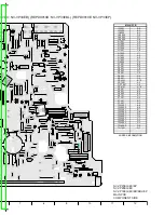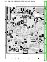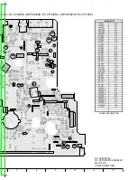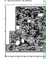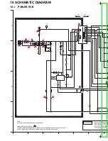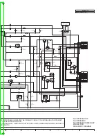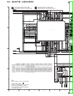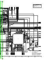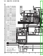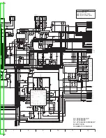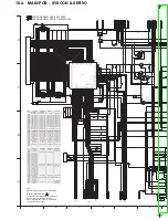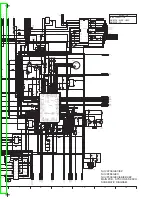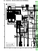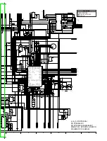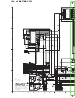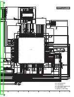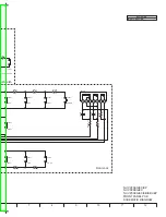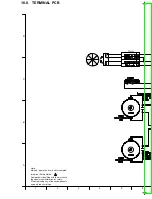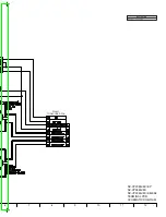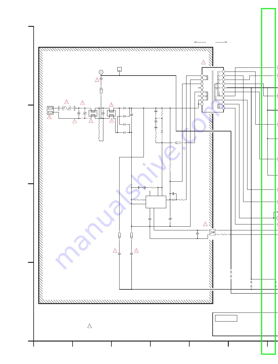
18 SCHEMATIC DIAGRAM
18.1. POWER PCB
A
B
C
D
1
2
3
4
5
6
Note:
Marked *(spare) parts are not assembled
Important Safety Notice:
Components identified with the mark have the special characteristics for safety.
When replacing any of these components use only the same type.
!
1
2
P1101
F1101
D1110
R1111
1M[0.25W, F]
R1110
1M[0.25W, F]
3
4
1
2
L1120
3
4
1
2
L1121
C1125
C1122
C1142
400V33[EB]
3
4
1
2
Q1200
R1206
270
D
2
IP1
C1124
LB1218
LB1214
D1106
C1106
$
L1102
EXCELDR35V
D1101
D1102
D1104
D1103
R1102
10[0.25W]
R1101
$100[1W]
C1102
$220p
C1103
$220p
R1
105
68K[2W]
D1
105
C1112
0.047
R1106
$
C1114
$
C1113
$
1
2
3
4
5
6
7
8
SoftS FB
VCC
D1
D2
N.C.
Isense
GND
IC1101
ZA1101
$
D
D
D
D
D
K1361
K1363
C1109
50V0.01[KB]
R1107
0.68[1W]
C1108
0.22[KB]
C1107
35V33[RJF]
R1103
330K[0.25W]
R1104
330K[0.25W]
D
20
19
18
17
16
15
14
13
12
2
3
4
5
6
7
8
9
11
B1
B2
P1
PT
P2
S8
S6
S4
SA
S5
S2
S7
S9
S3
S1
T1150
C1126
LB1217
C1123
K
ZA1103
ZA1104
HOT
COLD
CAUTION
THE STRIPED FRA
FROM THE SECON
PAY ATTENTION N
THE PRODUCTS.
ZA1104
+
Summary of Contents for NV-VP23-33
Page 13: ...C Stop unloading just before unloading would be completed D Then the tape becomes slack 13 ...
Page 22: ...7 9 MAIN PCB UNIT 1 Unscrew the Screws 2 Release the Connectors 3 Remove the Main PCB Unit 22 ...
Page 39: ...10 3 FRONT HOLDER 1 Remove the Front Holder 10 4 CLAMP PLATE UNIT 39 ...
Page 56: ...12 ABBREVIATIONS 56 ...
Page 64: ...20 1 VCR CHASSIS PARTS SECTION 20 2 DVD CHASSIS PARTS SECTION 64 ...
Page 65: ...20 3 CASING PARTS SECTION 65 ...
Page 66: ...66 ...
Page 67: ...20 4 PACKING PARTS SECTION 67 ...

