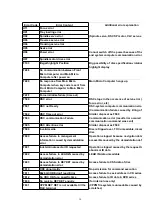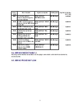
Error Code
Error Content
Additional error explanation
U11
Focus error
H01
Tray loading error
H02
Spindle servo error
(Spindle servo, DSC SP motor, CLV servo error)
H03
Traverse servo error
H04
Tracking servo error
H05
Seek error
H06
Power error
Cannot switch off the power because of the
and system computer communication error
H07
Spindle motor drive error
F103
Illegal highlight Position
Big possibility of disc specification violation
highlight display
F498
No communication between Front
Micro Computer and Main Micro
Computer after power on
F499
No response from Main Micro
Computer when key code is sent from
Front Micro Computer to Main Micro
Computer
Main Micro Computer hangs up
F4FF
Force initialize failure (time out)
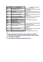
F500
DSC error
DSC stops in the occurence of servo error (
focus error, etc)
F501
DSC not Ready
DSC-system computer communication error
(Communication failure caused by idling of
F502
DSC Time out error
Similar disposal as F500
F503
DSC communication Failure
Communication error (result error occured
communication command was sent)
F505
DSC Attention error
Similar disposal as F500
F506
Invalid media
Disc is flipped over, TOC unreadable, incompatible
disc
F600
Access failure to management
information caused by demodulation
error
Operation stopped because navigation data
accessible caused by the demodulation defect
F601
Indeterminate sector ID requested
Operation stopped caused by the request to
abnormal ID data
F602
Access failure to LEAD-IN caused by
demodulation error
LEAD IN data unreadable
F603
Access failure to KEYDET caused by
demodulation error
Access failure to CSS data of disc
F610
ODC abnormality
No permission for command execution
F611
6626 QCODE don’t read Error
Access failure to seek address in CD series
F612
No CRC OK for a specific time
Access failure to ID data in DVD series
F630
No reply to KEY DET enquiry
(for internal use only)
F631
CPPM KEY DET is not available till the
FILE terminal
(CPPM file system is unreadable caused by
scratches)
30
Summary of Contents for NV-VP23-33
Page 13: ...C Stop unloading just before unloading would be completed D Then the tape becomes slack 13 ...
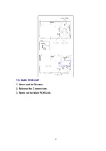
Page 22: ...7 9 MAIN PCB UNIT 1 Unscrew the Screws 2 Release the Connectors 3 Remove the Main PCB Unit 22 ...
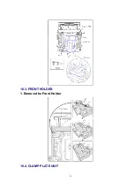
Page 39: ...10 3 FRONT HOLDER 1 Remove the Front Holder 10 4 CLAMP PLATE UNIT 39 ...
Page 56: ...12 ABBREVIATIONS 56 ...
Page 64: ...20 1 VCR CHASSIS PARTS SECTION 20 2 DVD CHASSIS PARTS SECTION 64 ...
Page 65: ...20 3 CASING PARTS SECTION 65 ...
Page 66: ...66 ...
Page 67: ...20 4 PACKING PARTS SECTION 67 ...

