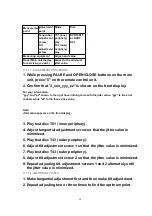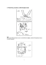
11.3.1.3. CHECK AFTER ADJUSTMENT
Play test disc or any other disc to make sure there is no picture degradation in the inner, middle
and outer peripheries and no audio skipping. After adjustment is finished, lock each adjustment
screw in position using screw lock.
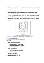
11.3.1.4. PROCEDURE FOR SCREW LOCK
1. After adjustment, remove top panel, tray, clamper base and
traverse unit in this sequence.
2. Lay the traverse unit upside down and fix adjustment screw with
screw lock.
3. After fixing, reassemble traverse unit, clamper base, tray and top
panel.
11.4. VCR ELECTRICAL ADJUSTMENT PROCEDURES
11.4.1. TEST EQUIPMENT
The following equipments are required for Electrical
Adjustments.
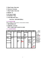
1. Dual-Trace Oscilloscope
- Voltage Range: 0.005-5V/div
- Frequency Range: DC-35MHz
- Probes: 10:1 / 1:1
2. Frequency Counter
- Frequency Range: 0-10MHz
- Probes: 1:1
3. Universal Counter
4. Digital Volt Meter (D.V.M.)
52
Summary of Contents for NV-VP23-33
Page 13: ...C Stop unloading just before unloading would be completed D Then the tape becomes slack 13 ...
Page 22: ...7 9 MAIN PCB UNIT 1 Unscrew the Screws 2 Release the Connectors 3 Remove the Main PCB Unit 22 ...
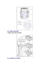
Page 39: ...10 3 FRONT HOLDER 1 Remove the Front Holder 10 4 CLAMP PLATE UNIT 39 ...
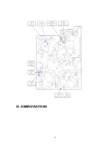
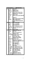
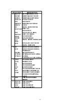
Page 56: ...12 ABBREVIATIONS 56 ...
Page 64: ...20 1 VCR CHASSIS PARTS SECTION 20 2 DVD CHASSIS PARTS SECTION 64 ...
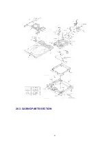
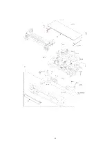
Page 65: ...20 3 CASING PARTS SECTION 65 ...
Page 66: ...66 ...
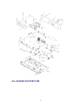
Page 67: ...20 4 PACKING PARTS SECTION 67 ...

