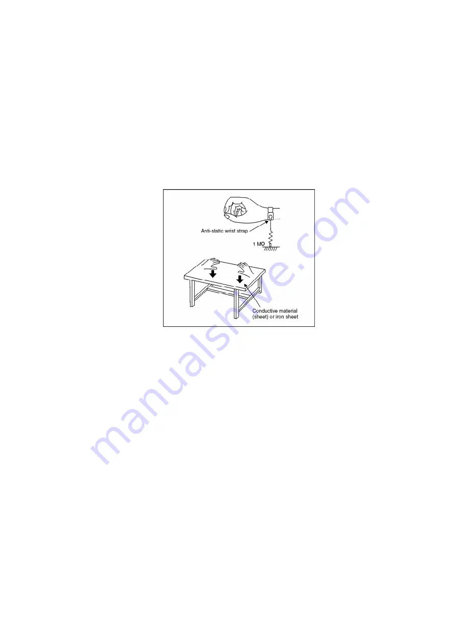
pickup will be damaged by static electricity in the working environment. Proceed servicing
works under the working environment where grounding works is completed.
5.1.1. WORKTABLE GROUNDING
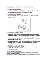
1. Put a conductive material (sheet) or iron sheet on the area where
the optical pickup is placed, and ground the sheet.
5.1.2. HUMAN BODY GROUNDING
1. Use the anti-static wrist strap to discharge the static electricity
form your body.
5.1.3. HANDLING OF OPTICAL PICKUP
1. To keep the good quality of the optical pickup maintenance parts
during transportation and before installation, the both ends of the
laser diode are short-circuited. After replacing the parts with new
ones, remove the short circuit according to the correct procedure.
(See this Technical Guide.)
2. Do not use a tester to check the laser diode for the optical pickup.
Failure to do so will damage the laser diode due to the power
supply in the tester.
6. GENERAL DESCRIPTION
6.1. OPERATING INSTRUCTIONS
6.2. SERVICE CAUTION
6.2.1. REPLACING IC6002/EEPROM
When the EEPROM: IC6002 is replaced, applicable model code, option code and electrical
adjustment data will not be available.
Therefore, enter and/or adjust the necessary data after replacing IC6002 by referring following
7
Summary of Contents for NV-VP23-33
Page 13: ...C Stop unloading just before unloading would be completed D Then the tape becomes slack 13 ...
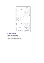
Page 22: ...7 9 MAIN PCB UNIT 1 Unscrew the Screws 2 Release the Connectors 3 Remove the Main PCB Unit 22 ...
Page 39: ...10 3 FRONT HOLDER 1 Remove the Front Holder 10 4 CLAMP PLATE UNIT 39 ...
Page 56: ...12 ABBREVIATIONS 56 ...
Page 64: ...20 1 VCR CHASSIS PARTS SECTION 20 2 DVD CHASSIS PARTS SECTION 64 ...
Page 65: ...20 3 CASING PARTS SECTION 65 ...
Page 66: ...66 ...
Page 67: ...20 4 PACKING PARTS SECTION 67 ...


