12
Connectors
Before connecting
!
Verify that all devices to be
connected up are unplugged from
the AC mains.
39
DVD OUT
COMPONENT VIDEO OUT
(PROGRESSIVE/
INTERLACE)
DVD/VHS
COMMON OUT
COAXIAL
DIGITAL AUDIO OUT
AUDIO
VIDEO
L
R
Y
P
B
P
R
AV1
(TV)
AV2
(DECODER/
EXT)
AUDIO
L
R
RF IN
RF OUT
AUDIO IN
L
R
COMPONENT VIDEO IN terminal
P
B
R
P
Red White
Y
40
38
DVD connectors
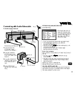
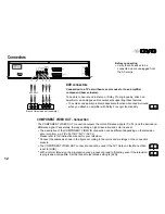
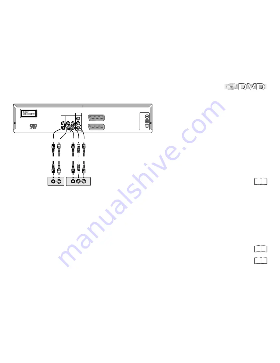
Connection to a TV set without a scart socket or to an amplifier
component (home cinema):
To be able to hear sound in stereo or Dolby Pro Logic quality, attach an
amplifier or an analogue audio component supporting these features.
!
To avoid sound quality problems deactivate function Advanced Surround
when you attach an amplifier with Dolby Pro Logic functionality.
Back of television set (example)
COMPONENT VIDEO OUT - Connection
The COMPONENT VIDEO OUT connection outputs the color-difference signals ( P
B
/P
R
) and the luminance-
difference signal Y separately, thereby enabling a higher resolution and color trueness.
!
The description of the COMPONENT VIDEO IN connection can be different depending on the television
set or monitor ( e.g. Y/P
B
/P
R
,Y/B-Y/R-Y, Y/C
B
/C
R
).
Please refer to the instruction manual for your television.
!
Connect the cables as shown in the figure according to the colors and markings on the connection
sockets.
D
The COMPONENT VIDEO OUT connection cannot be used if the AV1 Output in the Menu Video
is set to [RGB].
D
With a normal television, the progressive scan process can lead to flickering even if the television
is progressive-compatible. Set the Video Output Mode setting to [625i].


