No.
Item/Part
Fig.
Removal (Screw)
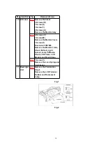
10 LCD Unit
Fig.13
Remove the Sheet.
3-Screws (R)
1-Screw (S)
1-Screw (T)
2-Screws (U)
Remove the Monitor Assy.
Fig.14
2-Screws (V)
1-Screw (W)
Remove the Monitor Cover.
1-Screw (X)
Disconnect CN7603.
Remove the Monitor C.B.A.,
Sheet (Reflect), Light
Screen, Lamp, Diffusion
Sheet, LCD Frame, LCD
Module and Shield Case.
Fig.14
1-Screw (Y)
Remove the Lock Spring and
Lock Lever.
11 Back light
Unit
Fig.15
Remove the Polarization
Sheet.
Remove the LCD Terminal
Rubber and Fluorescent
Lump.
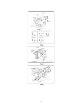
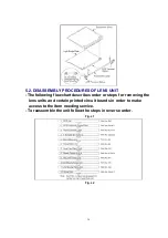
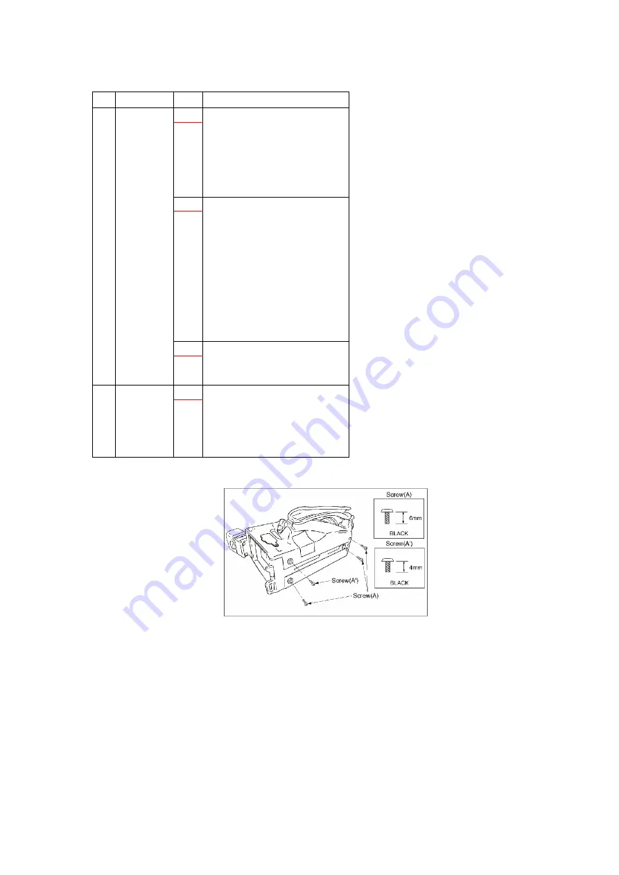
Fig.1
Fig.2
10
Summary of Contents for NV-VZ14EG
Page 8: ...5 ADJUSTMENT PROCEDURES 5 1 DISASSEMBLY PROCEDURES Flow Chart for Disassembly Procedure 8 ...
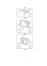
Page 11: ...Fig 3 Fig 4 Fig 5 11 ...
Page 12: ...Fig 6 Fig 7 Fig 8 12 ...
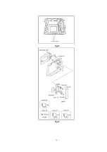
Page 13: ...Fig 9 Fig 10 Fig 11 Fig 12 13 ...
Page 14: ...Fig 13 Fig 14 14 ...
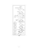
Page 15: ...Fig 15 15 ...
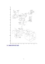
Page 20: ...9 3 MONITOR SECTION 20 ...
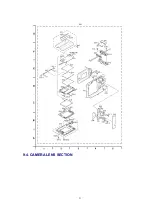
Page 21: ...9 4 CAMERA LENS SECTION 21 ...
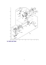
Page 22: ...9 5 EVF SECTION 22 ...
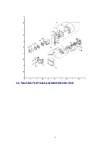
Page 23: ...9 6 PACKING PARTS ACCESSORIES SECTION 23 ...


