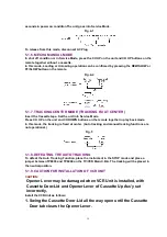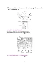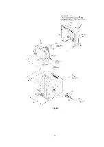
2. Make sure that all guide tabs are aligned properly. Then, press the
VCR Unit straight in.
Fig. 6
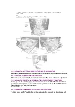
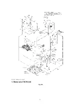
5.1.10. F.F.C. CONNECTION NOTE
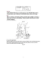
5.1.10.1. F.F.C. between the Capstan Motor and the Cylinder
Be careful with the direction of F.F.C. to connector as shown.
Fig. 7
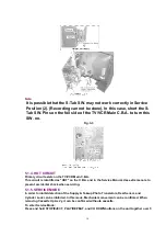
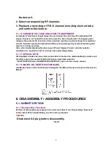
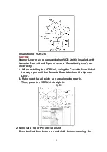
5.1.11. WIRE AND LEAD POSITION DIAGRAM
Fig. 8
16
Summary of Contents for OmniVision PV-C1324-K
Page 10: ...Fig 1 4 Fig 1 5 10 ...
Page 11: ...Fig 1 6 11 ...
Page 19: ...6 1 2 Disassembly Method Fig D2 19 ...
Page 20: ...Fig D3 20 ...
Page 21: ...6 1 2 1 Notes in chart 1 Removal of VCR Unit Fig D4 21 ...
Page 39: ...39 ...
Page 41: ...11 2 CHASSIS FRAME SECTION 1 41 ...
Page 42: ...11 3 CHASSIS FRAME SECTION 2 42 ...
Page 43: ...11 4 PACKING PARTS AND ACCESSORIES SECTION 43 ...
Page 60: ...R6079 ERJ6GEYJ102V MGF CHIP 1 10W 1K 60 ...
Page 65: ...C3035 ECJ2VC1H330J C CHIP 50V 33PF 65 ...
Page 74: ...13 2 CHASSIS FRAME SECTION 1 74 ...
Page 75: ...13 3 CHASSIS FRAME SECTION 2 75 ...
Page 76: ...13 4 PACKING PARTS AND ACCESSORIES SECTION 76 ...
Page 89: ...R554 ERDS2TJ123 CARBON 1 4W 12K 89 ...

