


15
TV Operation
STOP 1 2 : 0 0AM
ABC
0 : 0 0 : 0 0
SP
STEREO
SAP
MONO
STOP 1 2 : 0 0AM
ABC
STEREO
SAP
MONO
STOP 1 2 : 0 0AM
ABC
STEREO
SAP
MONO
k List
made.
d in.
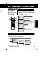
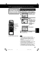
Receivable Broadcast Types
The following are possible audio broadcast types and
on-screen displays. The signal being received is indicated with
an “ ” mark while the selected audio mode is indicated with an
arrow. To change the audio mode for these broadcasts, see the
“Select Audio Mode for TV Viewing” section (below.)
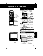
Press DISPLAY to display
the broadcast signal being received.
MTS Stereo and SAP broadcast
Multi-channel Television Sound Stereo
(main language) and Secondary Audio
Program (sub language) broadcasts are
being received simultaneously. Select
the STEREO or SAP audio mode.
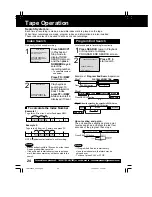
MTS Stereo broadcast
Multi-channel Television Sound Stereo
broadcast. Select STEREO audio mode.
• If stereo broadcast is weak and the
display flickers, select MONO audio
mode for possibly better results.
SAP broadcast
Secondary Audio Program
(sub language).
Select SAP audio mode for the sub
language.
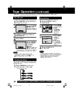
Select Audio Mode for TV Viewing
Press AUDIO to select the desired audio mode as described above.
(Arrow shows selection.)
• Each press of AUDIO will change the audio mode as shown below.
• “SAP” is selected with first press of AUDIO.
MTS Broadcast/TV Stereo System
MONO broadcast
Normal monaural sound broadcast.
STOP 1 2 : 0 0AM
ABC
STEREO
SAP
MONO
STOP 1 2 : 0 0AM
ABC
0 : 0 0 : 0 0
SP
STEREO
SAP
MONO
STOP 1 2 : 0 0AM
ABC
STEREO
SAP
MONO
STOP 1 2 : 0 0AM
ABC
STEREO
SAP
MONO
< Example >
Press AUDIO
Press AUDIO
Press AUDIO
Equipped with
®
-TV Noise
Reduction for true MTS
reproduction.
®
-TV Noise
Reduction is required for good
stereo separation and audio
fidelity.
®
is a registered
trademark, and is licensed by
®
Technology Licensing.
IMPORTANT NOTE:
• This stereo system is designed for TV viewing only. Recording
and playback will always be in monaural.
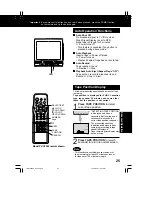
DISPLAY
AUDIO
POWER
MUTE
VOL
UP/DOWN
100 KEY
NITE
RAPID
TUNE
CH
NUMBER
Keys
For Model PV-C2062 only
LSQT0582A_P10-21.p65
12/14/2001, 2:04 PM
15
Summary of Contents for Omnivision PV-C2542
Page 22: ...6 1 2 Disassembly Method Fig D2 22 ...
Page 23: ...Fig D3 23 ...
Page 24: ...6 1 2 1 Notes in chart 1 Removal of VCR Unit Fig D4 24 ...
Page 28: ...6 2 2 Inner Parts Location Fig J1 1 28 ...
Page 29: ...6 2 3 EJECT Position Confirmation Fig J1 2 29 ...
Page 30: ...6 2 4 Full Erase Head and Cylinder Unit Fig J2 30 ...
Page 70: ...70 ...
Page 73: ...11 2 MECHANISM BOTTOM SECTION 73 ...
Page 74: ...11 3 CASSETTE UP COMPARTMENT SECTION 74 ...
Page 75: ...11 4 CHASSIS FRAME SECTION 1 75 ...
Page 76: ...11 5 CHASSIS FRAME SECTION 2 76 ...
Page 77: ...11 6 PACKING PARTS AND ACCESSORIES SECTION 77 ...
Page 84: ...121 LSPG1279 PACKING CASE PAPER F 6 84 ...
Page 97: ...R5317 ERDS2TJ101 CARBON 1 4W 100 97 ...
Page 99: ...R6045 ERJ6GEYJ102V MGF CHIP 1 10W 1K 99 ...
Page 118: ...R5401 ERJ6GEYJ561V MGF CHIP 1 10W 560 118 ...


