


110 (Cold chassis ground)
(For model with 25 inch CRT)
B+ Line
Minimum Resistance
125.0 V
1 k (Cold chassis ground)
27.0 V
180 (Cold chassis ground)
17.0 V
110 (Cold chassis ground)
6. When the TV set is not used for a long period of time, unplug the
power cord from the AC outlet.
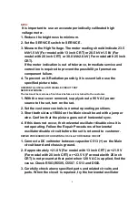
7. Potentials, as high as 25.0 kV (For model with 13 inch CRT) or 30.0
kV (For model with 20 inch CRT) or 32.0 kV (For model with 25
inch CRT) are present when this TV set is in operation. Operation
of the TV set without the rear cover involvesthe danger of a shock
hazard from the TV set power supply. Servicing should not be
attempted by anyone who is not thoroughly familiar with the
precautions necessary when working on high voltage equipment.
Always discharge the anode of the picture tubeto the CRT ground
of receiver before handling the tube.
8. After servicing make the following leakage current checks to
prevent the customer from being exposed to shock hazards.
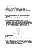
LEAKAGE CURRENT COLD CHECK
1. Unplug the AC cord and connect a jumper between the two prongs
on the plug.
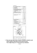
2. For physically operated power switches, turn power on. Otherwise
skip step 2.
3. Measure the resistance value, with an ohmmeter, between the
jumpered AC plug and each exposed metallic cabinet part on the
receiver, such as screwheads, connectors, etc. When the exposed
metallic part has a return path to the chassis, the readingshould
be between 1 M and 12 M . When the exposed metal does not
have a return path to the chassis, the reading must be infinity.
4
Summary of Contents for Omnivision PV-C2542
Page 22: ...6 1 2 Disassembly Method Fig D2 22 ...
Page 23: ...Fig D3 23 ...
Page 24: ...6 1 2 1 Notes in chart 1 Removal of VCR Unit Fig D4 24 ...
Page 28: ...6 2 2 Inner Parts Location Fig J1 1 28 ...
Page 29: ...6 2 3 EJECT Position Confirmation Fig J1 2 29 ...
Page 30: ...6 2 4 Full Erase Head and Cylinder Unit Fig J2 30 ...
Page 70: ...70 ...
Page 73: ...11 2 MECHANISM BOTTOM SECTION 73 ...
Page 74: ...11 3 CASSETTE UP COMPARTMENT SECTION 74 ...
Page 75: ...11 4 CHASSIS FRAME SECTION 1 75 ...
Page 76: ...11 5 CHASSIS FRAME SECTION 2 76 ...
Page 77: ...11 6 PACKING PARTS AND ACCESSORIES SECTION 77 ...
Page 84: ...121 LSPG1279 PACKING CASE PAPER F 6 84 ...
Page 97: ...R5317 ERDS2TJ101 CARBON 1 4W 100 97 ...
Page 99: ...R6045 ERJ6GEYJ102V MGF CHIP 1 10W 1K 99 ...
Page 118: ...R5401 ERJ6GEYJ561V MGF CHIP 1 10W 560 118 ...