Note:
In early units, a washer is used. When servicing the washer or the
P5 Arm Unit, replace only the P5 Arm Unit with a new one, and
remove the washer.
6.2.12.1. Reassembly Notes
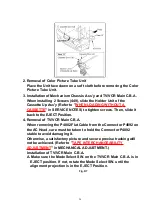
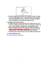
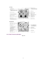
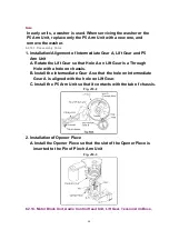
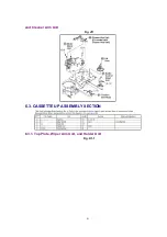
1. Installation/Alignment of Intermediate Gear A, Lift Gear and P5
Arm Unit
A. Rotate the Lift Gear so that Hole A on Lift Gear is a Through
Hole with a hole on chassis.
B. Install the Intermediate Gear A so that the hole on Intermediate
Gear A is aligned with the hole on Lift Gear.
C. Install the P5 Arm Unit so that it contacts with the tab of chassis.
Fig. J10-2
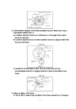
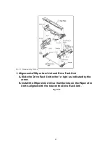
2. Installation of Opener Piece
A. Install the Opener Piece so that the slot of the Opener Piece is
inserted to the Pin of Pinch Arm Unit
Fig. J10-3
6.2.13. Motor Block Unit, Audio Control Head Unit, Lift Gear, Tension Arm Boss,
40
Summary of Contents for Omnivision PV-C2542
Page 22: ...6 1 2 Disassembly Method Fig D2 22 ...
Page 23: ...Fig D3 23 ...
Page 24: ...6 1 2 1 Notes in chart 1 Removal of VCR Unit Fig D4 24 ...
Page 28: ...6 2 2 Inner Parts Location Fig J1 1 28 ...
Page 29: ...6 2 3 EJECT Position Confirmation Fig J1 2 29 ...
Page 30: ...6 2 4 Full Erase Head and Cylinder Unit Fig J2 30 ...
Page 70: ...70 ...
Page 73: ...11 2 MECHANISM BOTTOM SECTION 73 ...
Page 74: ...11 3 CASSETTE UP COMPARTMENT SECTION 74 ...
Page 75: ...11 4 CHASSIS FRAME SECTION 1 75 ...
Page 76: ...11 5 CHASSIS FRAME SECTION 2 76 ...
Page 77: ...11 6 PACKING PARTS AND ACCESSORIES SECTION 77 ...
Page 84: ...121 LSPG1279 PACKING CASE PAPER F 6 84 ...
Page 97: ...R5317 ERDS2TJ101 CARBON 1 4W 100 97 ...
Page 99: ...R6045 ERJ6GEYJ102V MGF CHIP 1 10W 1K 99 ...
Page 118: ...R5401 ERJ6GEYJ561V MGF CHIP 1 10W 560 118 ...

