


is at maximum.
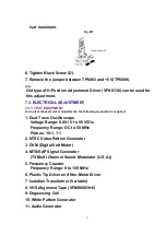
Fig. M7
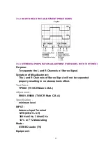
6. Tighten Black Screw (D).
7. Remove the jumper between TP6003 and +5 V(TP6009).
Note:
Old type of H-Position Adjustment Driver (VFK0136) can be used for
this adjustment.
7.3. ELECTRICAL ADJUSTMENT
7.3.1. TEST EQUIPMENT
To do all of these electrical adjustments, the following equipment is required.
1. Dual-Trace Oscilloscope
Voltage Range: 0.001 V to 50 V/Div.
Frequency Range: DC to 50 MHz
Probes: 10:1, 1:1
2. NTSC Video Pattern Generator
3. DVM (Digital Volt Meter)
4. MTS/SAP Signal Generator
(TV Multi-Channel Sound Modulator (U.S.A.))
5. Frequency Counter
Frequency Range: 0 to 150 MHz
6. Plastic Tip Driver and Non-Metal Driver
7. Isolation Transformer (Variable)
8. VHS Alignment Tape (VFMS0003H6)
9. Degaussing Coil
10. White Pattern Generator
11. Audio Generator
51
Summary of Contents for Omnivision PV-C2542
Page 22: ...6 1 2 Disassembly Method Fig D2 22 ...
Page 23: ...Fig D3 23 ...
Page 24: ...6 1 2 1 Notes in chart 1 Removal of VCR Unit Fig D4 24 ...
Page 28: ...6 2 2 Inner Parts Location Fig J1 1 28 ...
Page 29: ...6 2 3 EJECT Position Confirmation Fig J1 2 29 ...
Page 30: ...6 2 4 Full Erase Head and Cylinder Unit Fig J2 30 ...
Page 70: ...70 ...
Page 73: ...11 2 MECHANISM BOTTOM SECTION 73 ...
Page 74: ...11 3 CASSETTE UP COMPARTMENT SECTION 74 ...
Page 75: ...11 4 CHASSIS FRAME SECTION 1 75 ...
Page 76: ...11 5 CHASSIS FRAME SECTION 2 76 ...
Page 77: ...11 6 PACKING PARTS AND ACCESSORIES SECTION 77 ...
Page 84: ...121 LSPG1279 PACKING CASE PAPER F 6 84 ...
Page 97: ...R5317 ERDS2TJ101 CARBON 1 4W 100 97 ...
Page 99: ...R6045 ERJ6GEYJ102V MGF CHIP 1 10W 1K 99 ...
Page 118: ...R5401 ERJ6GEYJ561V MGF CHIP 1 10W 560 118 ...


