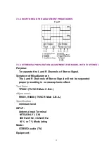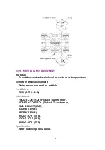
7.3.8. FOCUS, SCREEN, CUT OFF, DRIVE ADJUSTMENT
Purpose:
To set the optimum Focus and Screen.
Symptom of Misadjustment:
The picture is out of Focus and there will be an improper screen
color mix.
Test Point :
TP50 (CRT C.B.A.)
Adjustment :
FOCUS CONTROL (Flyback Transformer),
SCREEN CONTROL (Flyback Transformer),
SUB BRIGHT (EVR),
B DRIVE (EVR),
G DRIVE (EVR),
B CUT -OFF (EVR),
G CUT -OFF (EVR),
R CUT -OFF (EVR)
Specification :
Refer to descriptions below.
INPUT :
Video Input Jack,
Monoscope Pattern Signal
Mode :
STOP
Equipment :
Oscilloscope,
NTSC Video Pattern Generator
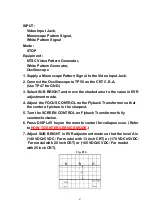
1. Supply a Monoscope Pattern Signal to the Video Input Jack.
2. Connect the Oscilloscope to TP50 on the CRT C.B.A.
(Use TP47 for GND.)
3. Select SUB BRIGHT and move the shaded area to the value in EVR
adjustment mode.
4. Adjust the FOCUS CONTROL on the Flyback Transformer so that
60
Summary of Contents for Omnivision PV-C2542
Page 22: ...6 1 2 Disassembly Method Fig D2 22 ...
Page 23: ...Fig D3 23 ...
Page 24: ...6 1 2 1 Notes in chart 1 Removal of VCR Unit Fig D4 24 ...
Page 28: ...6 2 2 Inner Parts Location Fig J1 1 28 ...
Page 29: ...6 2 3 EJECT Position Confirmation Fig J1 2 29 ...
Page 30: ...6 2 4 Full Erase Head and Cylinder Unit Fig J2 30 ...
Page 70: ...70 ...
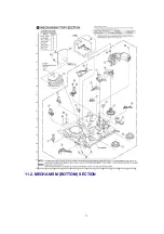
Page 73: ...11 2 MECHANISM BOTTOM SECTION 73 ...
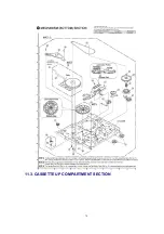
Page 74: ...11 3 CASSETTE UP COMPARTMENT SECTION 74 ...
Page 75: ...11 4 CHASSIS FRAME SECTION 1 75 ...
Page 76: ...11 5 CHASSIS FRAME SECTION 2 76 ...
Page 77: ...11 6 PACKING PARTS AND ACCESSORIES SECTION 77 ...
Page 84: ...121 LSPG1279 PACKING CASE PAPER F 6 84 ...
Page 97: ...R5317 ERDS2TJ101 CARBON 1 4W 100 97 ...
Page 99: ...R6045 ERJ6GEYJ102V MGF CHIP 1 10W 1K 99 ...
Page 118: ...R5401 ERJ6GEYJ561V MGF CHIP 1 10W 560 118 ...

