

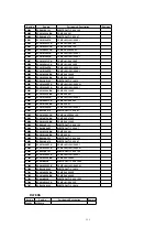


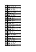


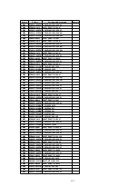


Ref. No.
Part No.
Part Name& Description
Remarks
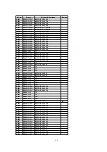
C9010
ECEA1HKA010
ELECTROLYTIC 50V 1
C9011
ECEA1CKA100
ELECTROLYTIC 16V 10
C9012
ECEA1CKA100
ELECTROLYTIC 16V 10
C9013
ECEA1CKA100
ELECTROLYTIC 16V 10
C9014
ECEA1EKN4R7
ELECTROLYTIC 25V 4.7
C9015
ECEA1HKA3R3
ELECTROLYTIC 50V 3.3
C9016
ECEA1EKN4R7
ELECTROLYTIC 25V 4.7
C9017
ECUV1E473KBN C CHIP 25V 0.047
C9018
ECUV1H272KBN C CHIP 50V 2700P
C9019
ECUV1H103ZFN C CHIP+80%-20% 50V 0.01
C9020
ECEA1CKA220
ELECTROLYTIC 16V 22
C9021
ECUV1H103ZFN C CHIP+80%-20% 50V 0.01
C9022
ECEA0JKA470
ELECTROLYTIC 6.3V 47
C9023
ECUV1H103ZFN C CHIP+80%-20% 50V 0.01
C9024
ECEA0JKA470
ELECTROLYTIC 6.3V 47
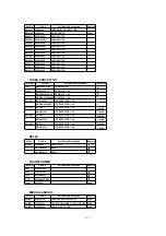
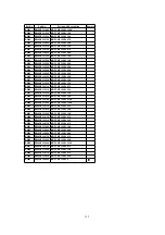
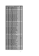
C9101
ECEA1EKA4R7
ELECTROLYTIC 25V 4.7
C9102
ECEA1EKA4R7
ELECTROLYTIC 25V 4.7
C9103
ECEA1EKA4R7
ELECTROLYTIC 25V 4.7
C9104
ECEA1EKA4R7
ELECTROLYTIC 25V 4.7
C9105
ECEA1CKA100
ELECTROLYTIC 16V 10
C9106
ECEA1HKA010
ELECTROLYTIC 50V 1
C9107
ECUV1H562KBN C CHIP 50V 5600P
C9108
ECUV1H123KBN C CHIP 50V 0.012
C9109
ECEA1EKN4R7
ELECTROLYTIC 25V 4.7
C9110
ECEA1HKA010
ELECTROLYTIC 50V 1
C9111
ECEA1CKA100
ELECTROLYTIC 16V 10
C9112
ECEA1CKA100
ELECTROLYTIC 16V 10
C9113
ECEA1CKA100
ELECTROLYTIC 16V 10
C9114
ECEA1EKN4R7
ELECTROLYTIC 25V 4.7
C9115
ECEA1HKA3R3
ELECTROLYTIC 50V 3.3
C9116
ECEA1EKN4R7
ELECTROLYTIC 25V 4.7
C9117
ECUV1H473KBN C CHIP 50V 0.047
C9118
ECUV1H272KBN C CHIP 50V 2700P
C9119
ECUV1H103ZFN C CHIP+80%-20% 50V 0.01
C9120
ECEA1CKA220
ELECTROLYTIC 16V 22
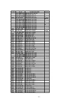
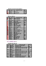
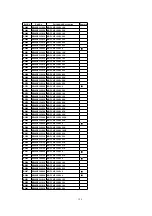
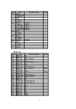
C9201
ECUV1H103ZFN C CHIP+80%-20% 50V 0.01
C9202
ECEA0JKA470
ELECTROLYTIC 6.3V 47
C9203
ECEA1CKA100
ELECTROLYTIC 16V 10
C9204
ECQP1H102J
PO-5% 50V 1000P
C9205
ECEA1HKA010
ELECTROLYTIC 50V 1
C9206
ECEA1HKA3R3
ELECTROLYTIC 50V 3.3
C9207
ECEA1HKA010
ELECTROLYTIC 50V 1
C9208
ECUV1H223KBN C CHIP 50V 0.022
C9209
ECUV1H223KBN C CHIP 50V 0.022
C9210
ECEA1HKA010
ELECTROLYTIC 50V 1
C9211
ECEA1HKA010
ELECTROLYTIC 50V 1
FILTERS
Ref. No.
Part No.
Part Name& Description
Remarks
FL4271
VLFS0014
FL4272
VLFS0014
119
Summary of Contents for OmniVision PV-C2780-K
Page 8: ...Fig 1 3 Fig 1 4 8 ...
Page 26: ...Fig D5 6 1 2 1 Notes in chart 26 ...
Page 29: ...6 2 2 Inner Parts Location Fig J1 1 29 ...
Page 30: ...6 2 3 EJECT Position Confirmation Fig J1 2 30 ...
Page 31: ...6 2 4 Grounding Plate Unit Full Erase Head and Cylinder Unit Fig J2 1 31 ...
Page 44: ...6 3 CASSETTE UP ASS Y SECTION 6 3 1 Top Plate Wiper Arm Unit and Holder Unit Fig K1 1 44 ...
Page 81: ...81 ...
Page 85: ...11 2 MECHANISM BOTTOM SECTION 85 ...
Page 86: ...11 3 CASSETTE UP COMPARTMENT SECTION 86 ...
Page 87: ...11 4 CHASSIS FRAME SECTION 1 87 ...
Page 88: ...11 5 CHASSIS FRAME SECTION 2 88 ...
Page 89: ...11 6 PACKING PARTS AND ACCESSORIES SECTION 89 ...