FM Radio
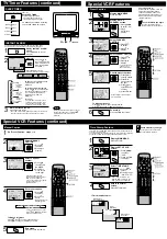
Special VCR Features (continued)
VIDEO IN
VIDEO IN
L-AUDIO IN-R
L-AUDIO IN-R
POWER
VOL
CH
STOP/EJECT
STOP/EJECT REW/
REW/
PLAY/REPEAT
PLAY/REPEAT FF/
FF/
REC
REC
TIMER/FM
TIMER/FM
ACTION
ACTION
REC
REC ON TIMER
ON TIMER PROG TIMER
PROG TIMER
Display Time Stamp Data.
1) Insert cassette with
record tab.
2) Press PLAY.
Changing Time Stamp Data
You may change the time stamp data (Date, Time, Channel, Category,
and Notes) as desired.
1
2
Display TIME STAMP
EDIT.
Press
PROG/VCR+
while the data is
displayed in
playback mode.
3
1) Press
to select.
2) Press or
to enter and
continue.
Change Time Stamp
Data.
T I ME STAMP ED I T
DATE : 12 / 2 7 / 1 9 9 9 MON
T I ME : 12 : 0 0PM - 1 : 0 0PM
CH : 0 8 ABC
CATEGORY : MOV I E
NOTES :
M
EMOR I AL MOV I E
- - --
- - - - - -- - -- - - - - - - - -- - -- - -
SELECT : KEY
SET : KEY
END : PROG KEY
• Characters in
NOTES will change
in the following order.
To Make Corrections
3) Repeat 1) and
2) as needed.
Press
to move to the
incorrect entry, then press
to make the correction.
4
Write the new data.
NOW WR I T I NG T I ME STAMP
Press
PROG/VCR+.
• After the data is written, the unit
automatically goes into Stop mode.
• You cannot use POWER or REC
button while “NOW WRITING
TIME STAMP” is displayed.
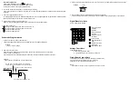
A B C Z BLANK &
9 2 1 0 / !
1
1
PLAY/REPEAT
Weak Signal Display ON/OFF
1
Display MAIN MENU.
Press ACTION*.
Display SET UP
CHANNEL screen.
1) Press
to select “CH.”
2) Press ACTION
to display.
Select WEAK SIGNAL
DISPLAY.
1) Press
to
select.
2) Press to
set “ON” or
“OFF.”
Return to the normal
screen.
Press ACTION twice.
2
When “ON” is selected, the picture is displayed even when a
broadcast signal is weak or non-existent.
4
3
• “ON” = Picture is displayed regardless of signal condition, and
may not always be clearly visible.
“OFF” = Screen turns solid blue when signal is absent or weak.
• If unit is connected to equipment which has blue back feature,
selecting “ON” will have no effect on the other equipment.
VCR Lock
All operations are prohibited except Timer recording and tape
eject. Useful for families with small children.
To turn “ON.”
In stop mode, hold
down REC on the
unit without a
cassette inserted for
7 seconds.
To turn “OFF.”
Repeat above with
or without cassette.
• VCR Lock is canceled automatically
after about 24 hours if clock is set.
Notes
ANTENNA : CABLE
AUTO SET
CHANNEL CAPT I ON
WEAK S
EAK S I GNAL
GNAL D I SPLAY
SPLAY : OFF
OFF
CABLE BOX SET UP
VCR P l u s+ CH SET UP
SELECT : KEY
SET : KEY
END : ACT I ON KEY
SET UP CHANNEL
REC
REC
VCR LOCK ACT I VATED
VCR LOCK OFF
M A I N MENU
CLOCK
C H
SET : ACT I ON KEY
SELECT : KEY
VCR
T V
EX I T
LANGUAGE
VIDEO IN
VIDEO IN
L-AUDIO IN-R
L-AUDIO IN-R
POWER
POWER
VOL
VOL
CH
CH
STOP/EJECT
STOP/EJECT REW/
REW/
PLAY/REPEAT
PLAY/REPEAT FF/
REC
REC
TIMER/FM
TIMER/FM
ACTION
ACTION
REC
REC ON TIMER
ON TIMER PROG TIMER
PROG TIMER
REC
VIDEO IN
VIDEO IN
L-AUDIO IN-R
L-AUDIO IN-R
POWER
POWER
VOL
VOL
CH
CH
STOP/EJECT
STOP/EJECT REW/
REW/
PLAY/REPEAT
PLAY/REPEAT FF/
FF/
REC
REC
TIMER/FM
TIMER/FM
ACTION
ACTION
REC
REC ON TIMER
ON TIMER PROG TIMER
PROG TIMER
2
FM Radio is ...
This unit has an FM radio with built-in
antenna, 9 station preset, and a band range
of 87.5 ~ 108.1 MHz. You can even set the
On-Timer to wake up to your favorite
radio station.
Display FM radio mode.
Press FM/TV* on the remote or
TIMER/FM twice on the unit.
Select the FM number.
1
Continued on the right...
Press a
NUMBERED key
(1~9.)
To Make Corrections,
select station with a NUMBERED key, then do step 3 again.
To exit FM mode, press FM/TV on the remote or
TIMER/FM twice on the unit.
Set the radio station.
1) Press CH
to select the
desired radio
station.
(Each press changes
frequency 200 kHz.)
2) Press ADD/DLT
to set.
Quick Station Scan
Hold down CH or for a few
seconds, then release to
scan for FM stations in your area.
• To cancel, press CH
or
while
in search mode.
3
FM ANTENNA Setup
a
Display MAIN MENU.
Press ACTION.
Display SET UP TV
screen.
1) Press
to select “TV.”
2) Press ACTION
to display.
b
Make sure FM tuning is done correctly
(See FM Radio Setup.)
FM Radio Setup
FM 1 87. 5MHz
1 2 : 0 0PM
FM 1 8 7. 7MHz
MEMORY : PUSH ADD / DLT KEY
1 2 : 0 0PM
FM 1 8 7. 7MHz
MEMOR I ZED
1 2 : 0 0PM
M A I N MENU
T V
VCR
EX I T
CLOCK
C H
LANGUAGE
SET : ACT I ON KEY
SELECT : KEY
TIMER/FM
1
SELECT : KEY
SET : KEY
END : ACT I ON KEY
SET UP FM
FM ANTENNA
FM ANTENNA
: INT
INT
FM TRANSMITTER
: ON
SET UP FM TRANSMITTER
SPKR W/FM TRANS
: OFF
• FM radio cannot be recorded on a Video
cassette.
• You may get better reception by
repositioning the unit.
• You cannot select FM Radio mode during
playback or record, or while a blue back
screen (PROG, ACTION, MENU) is
displayed.
• PIP function cannot be used while in FM
mode.
Notes
d
e
Select FM ANTENNA.
1) Press
to
select.
2) Press to
select “INT
(INTERNAL)
” or
“EXT
(EXTERNAL)
”
whichever
sounds the best.
End setup.
Press ACTION three times
to exit.
For cable TV users
“
INT”
For antenna users
“
EXT”
s
VIDEO IN
VIDEO IN
L-AUDIO IN-R
L-AUDIO IN-R
POWER
POWER
VOL
VOL
CH
CH
STOP/EJECT
STOP/EJECT REW/
REW/
PLAY/REPEAT
PLAY/REPEAT FF/
FF/
REC
REC
TIMER/FM
TIMER/FM
ACTION
ACTION
REC
REC ON TIMER
ON TIMER PROG TIMER
PROG TIMER
TIMER/FM
A
To select Audio Mode for FM Radio
Select “STEREO” or “MONO.”
Press AUDIO
repeatedly in FM
Radio mode.
STEREO
MONO
FM 1 8 7. 7MHz
1 2 : 0 0PM
B
Display FM radio mode.
Press FM/TV on the remote or
TIMER/FM twice on the unit.
A
To cancel, press FM/TV on the remote or TIMER/FM
twice on the unit.
Select the FM number.
Press a
NUMBERED key
(1~9) to select a
preset station
(see steps 2 and
3 on the previous
section.)
Once stations are set, the selected station and current time are displayed
when FM Radio mode is entered. To remove time, press DISPLAY.
If DISPLAY is pressed, the unit status screen appears.
Notes
Using FM Radio
FM 1 87. 5MHz
1 2 : 0 0PM
c
Select SET UP FM.
1) Press
to
select.
2) Press to
display.
SELECT : KEY
SET : KEY
END : ACT I ON KEY
SET UP TV
PIP SIZE : NORMAL
LOCK
CAPT I ON
I NPUT SELECT : TUNER
V I DEO ADJUST
SET UP FM
SET UP FM
SPEAKER : ON
CH
Summary of Contents for OmniVision PV-C2780-K
Page 8: ...Fig 1 3 Fig 1 4 8 ...
Page 26: ...Fig D5 6 1 2 1 Notes in chart 26 ...
Page 29: ...6 2 2 Inner Parts Location Fig J1 1 29 ...
Page 30: ...6 2 3 EJECT Position Confirmation Fig J1 2 30 ...
Page 31: ...6 2 4 Grounding Plate Unit Full Erase Head and Cylinder Unit Fig J2 1 31 ...
Page 44: ...6 3 CASSETTE UP ASS Y SECTION 6 3 1 Top Plate Wiper Arm Unit and Holder Unit Fig K1 1 44 ...
Page 81: ...81 ...
Page 85: ...11 2 MECHANISM BOTTOM SECTION 85 ...
Page 86: ...11 3 CASSETTE UP COMPARTMENT SECTION 86 ...
Page 87: ...11 4 CHASSIS FRAME SECTION 1 87 ...
Page 88: ...11 5 CHASSIS FRAME SECTION 2 88 ...
Page 89: ...11 6 PACKING PARTS AND ACCESSORIES SECTION 89 ...


