


C359
C358
C360
1000P
C354
680P
C353
560P
C352
560P
C351
C357
J351
2SC3063
2SC3063
2SC3063
3300
R358
330
R361
330
R362
100
R365
100
R363
3300
R359
3300
R357
330
R360
100
R364
15K
R353
R366 31
15K
R352
15K
R351
R367
2700
R355
2700
R354
2700
R356
D351
C356
G1
G1
KG
7
KR
7
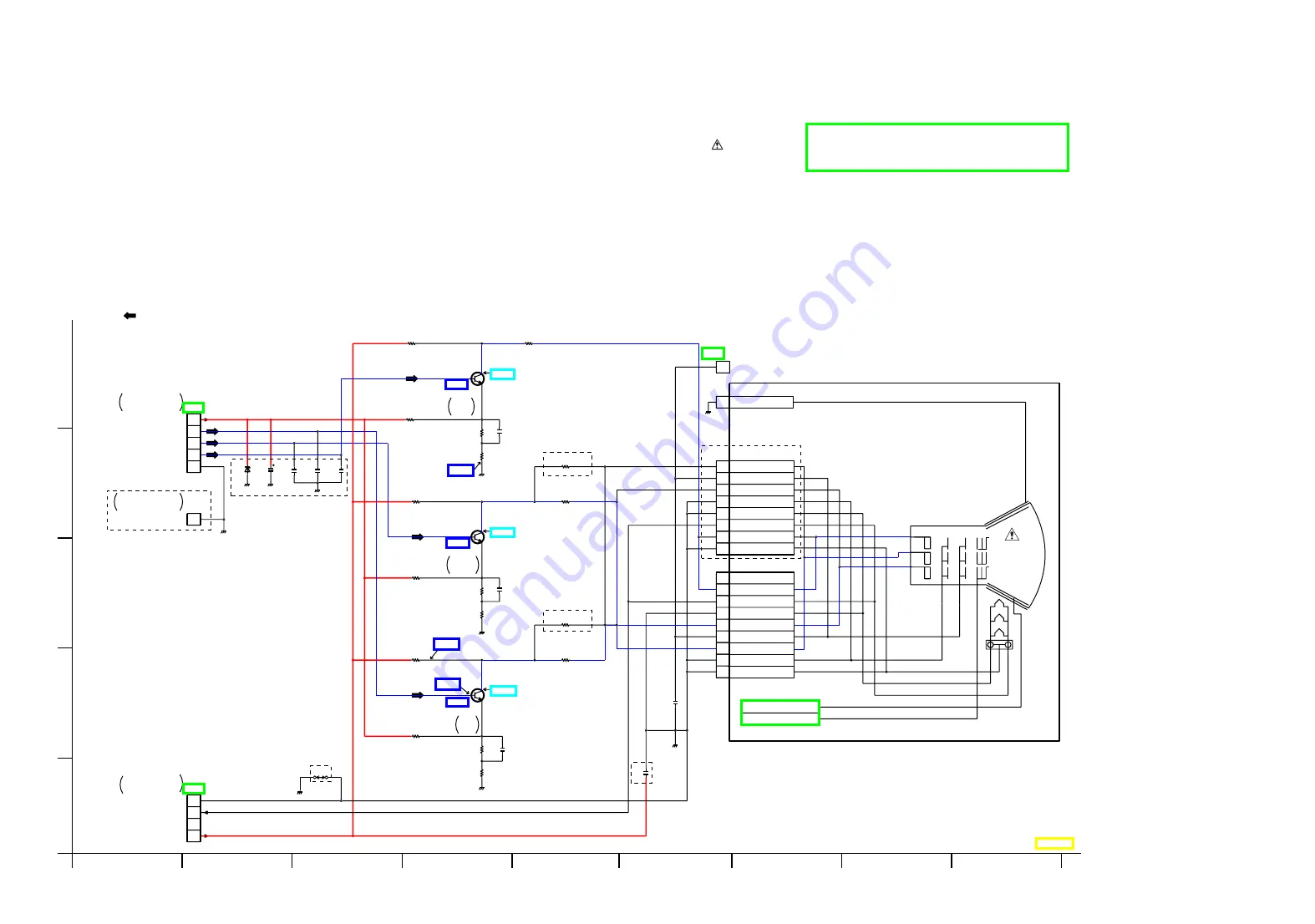
PICTURE TUBE
G1
2
6
5
9
KG
GND
KR
2
HEATER GND
KR
KG
8
E
4
E
HEATER
KB
5
1
HEATER
6
4
1
KB
3
KB
G2
G2
1
HEATER GND
G2
8
3
VIDEO SIGNAL
1
2
3
4
5
GND
SW +12V
GREEN
BLUE
RED
1
GND
3
4
1
2
GND
HEATER
200V
P356
IC
SCREEN
1
P354
P355
P353
BLUE
AMP
AMP
GREEN
AMP
RED
3
A
E
G
1
A
B
C
I
4
5
2
F
H
D
CRT SOCKET
Z
Z
Z
2W
2W
2W
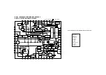
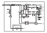
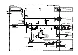
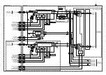
UNLESS OTHERWISE SPECIFIED:
WATTAGE OF RESISTORS IS 1/4W
Z
2KV
Z
TO TV PROCESS
C.B.A. P5301
TO TV/VCR MAIN
C.B.A. P558
TO TV/VCR MAIN
C.B.A. P552
(TO TV/VCR MAIN C.B.A.)
(TO TV/VCR MAIN C.B.A.)
Z
Z
FOR SCHEMATIC DIAGRAM AND CIRCUIT BOARD LAYOUT NOTES,
REFER TO BEGINNING OF SCHEMATIC SECTION.
IMPORTANT SAFETY NOTICE:
COMPONENTS IDENTIFIED BY THE SIGN HAVE
SPECIAL CHARACTERISTICS IMPORTANT FOR SAFETY.
WHEN REPLACING ANY OF THESE COMPONENTS,
USE ONLY THE SPECIFIED PARTS.
NOTE:
PARTS ENCLOSED IN DASHED LINES MARKED "Z" ARE NOT USED.
Summary of Contents for OmniVision PV-C2780-K
Page 8: ...Fig 1 3 Fig 1 4 8 ...
Page 26: ...Fig D5 6 1 2 1 Notes in chart 26 ...
Page 29: ...6 2 2 Inner Parts Location Fig J1 1 29 ...
Page 30: ...6 2 3 EJECT Position Confirmation Fig J1 2 30 ...
Page 31: ...6 2 4 Grounding Plate Unit Full Erase Head and Cylinder Unit Fig J2 1 31 ...
Page 44: ...6 3 CASSETTE UP ASS Y SECTION 6 3 1 Top Plate Wiper Arm Unit and Holder Unit Fig K1 1 44 ...
Page 81: ...81 ...
Page 85: ...11 2 MECHANISM BOTTOM SECTION 85 ...
Page 86: ...11 3 CASSETTE UP COMPARTMENT SECTION 86 ...
Page 87: ...11 4 CHASSIS FRAME SECTION 1 87 ...
Page 88: ...11 5 CHASSIS FRAME SECTION 2 88 ...
Page 89: ...11 6 PACKING PARTS AND ACCESSORIES SECTION 89 ...


