


(266°F ~ 302°F)
(130°C ~150°C) for about two minutes.
Note:
A. Leadless components must not be reused after removal.
B. Excessive mechanical stress and rubbing of the component
electrode must be avoided.
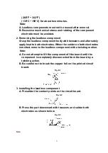
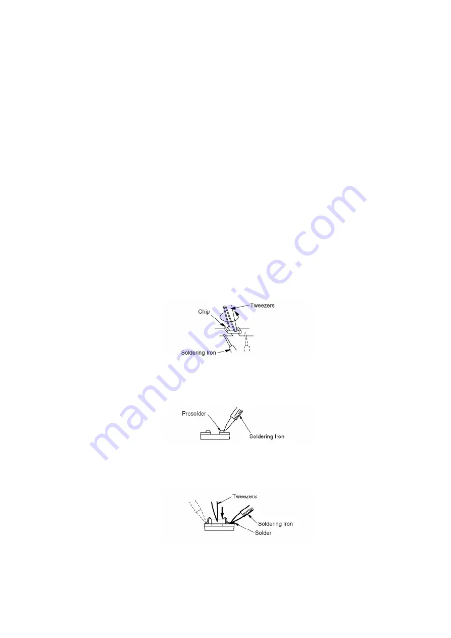
2. Removing the leadless component
Grasp the leadless component body with tweezers and alternately
apply heat to both electrodes. When the solder on both electrodes
is melted, remove the leadless component with a twisting motion.
Note:
A. Do not attempt to lift the component off the board until the
component is completely disconnected from the board by a
twisting action.
B. Be careful not to break the copper foil on the printed circuit
board.
Fig. 9-1
3. Installing the leadless component
A. Presolder the contact points on the circuit board.
Fig. 9-2
B. Press the part downward with tweezers and solder both
electrodes as shown below.
Fig. 9-3
Note:
21
Summary of Contents for OmniVision PV-C2780-K
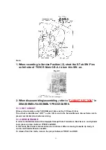
Page 8: ...Fig 1 3 Fig 1 4 8 ...
Page 26: ...Fig D5 6 1 2 1 Notes in chart 26 ...
Page 29: ...6 2 2 Inner Parts Location Fig J1 1 29 ...
Page 30: ...6 2 3 EJECT Position Confirmation Fig J1 2 30 ...
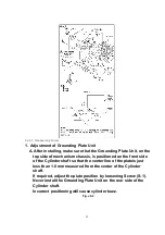
Page 31: ...6 2 4 Grounding Plate Unit Full Erase Head and Cylinder Unit Fig J2 1 31 ...
Page 44: ...6 3 CASSETTE UP ASS Y SECTION 6 3 1 Top Plate Wiper Arm Unit and Holder Unit Fig K1 1 44 ...
Page 81: ...81 ...
Page 85: ...11 2 MECHANISM BOTTOM SECTION 85 ...
Page 86: ...11 3 CASSETTE UP COMPARTMENT SECTION 86 ...
Page 87: ...11 4 CHASSIS FRAME SECTION 1 87 ...
Page 88: ...11 5 CHASSIS FRAME SECTION 2 88 ...
Page 89: ...11 6 PACKING PARTS AND ACCESSORIES SECTION 89 ...


