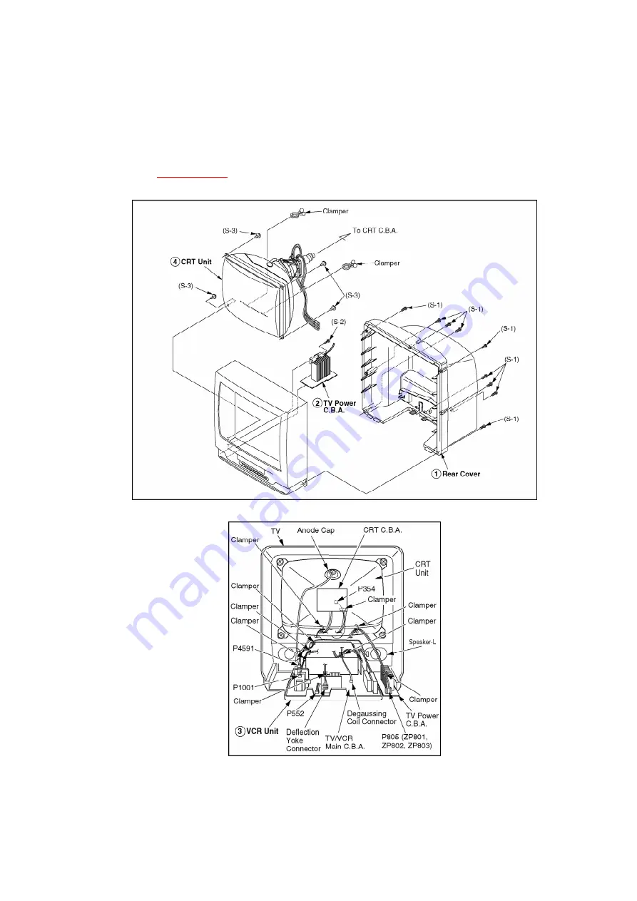
B: Part to be removed or installed.
C: Fig. No. showing Procedure or Part Location.
D: Identification of part to be removed, unhooked, unlocked, released, unplugged or unsoldered.
6(S-1)= 6 Screws (S-1), 6(L-1)= 6 Locking Tabs (L-1),
(P-1)= Spring (P-1)
E: Refer to "
Notes in chart
."
Fig. D2
Fig. D3
Fig. D4
25
Summary of Contents for OmniVision PV-C2780-K
Page 8: ...Fig 1 3 Fig 1 4 8 ...
Page 26: ...Fig D5 6 1 2 1 Notes in chart 26 ...
Page 29: ...6 2 2 Inner Parts Location Fig J1 1 29 ...
Page 30: ...6 2 3 EJECT Position Confirmation Fig J1 2 30 ...
Page 31: ...6 2 4 Grounding Plate Unit Full Erase Head and Cylinder Unit Fig J2 1 31 ...
Page 44: ...6 3 CASSETTE UP ASS Y SECTION 6 3 1 Top Plate Wiper Arm Unit and Holder Unit Fig K1 1 44 ...
Page 81: ...81 ...
Page 85: ...11 2 MECHANISM BOTTOM SECTION 85 ...
Page 86: ...11 3 CASSETTE UP COMPARTMENT SECTION 86 ...
Page 87: ...11 4 CHASSIS FRAME SECTION 1 87 ...
Page 88: ...11 5 CHASSIS FRAME SECTION 2 88 ...
Page 89: ...11 6 PACKING PARTS AND ACCESSORIES SECTION 89 ...

