


6.2.4.1. Reassembly Notes
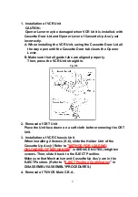
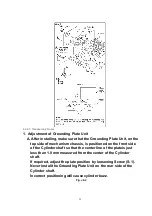
1. Adjustment of Grounding Plate Unit
A. After installing, make sure that the Grounding Plate Unit, on the
top side of mechanism chassis, is positioned on the front side
of the Cylinder shaft so that the center line of the plateis just
less than 1.0 mm measured from the center of the Cylinder
shaft.
If required, adjust the plate position by loosening Screw (S-1).
Never install the Grounding Plate Unit on the rear side of the
Cylinder shaft.
Incorrect positioning will cause cylinder buzz.
Fig. J2-2
32
Summary of Contents for OmniVision PV-C2780-K
Page 8: ...Fig 1 3 Fig 1 4 8 ...
Page 26: ...Fig D5 6 1 2 1 Notes in chart 26 ...
Page 29: ...6 2 2 Inner Parts Location Fig J1 1 29 ...
Page 30: ...6 2 3 EJECT Position Confirmation Fig J1 2 30 ...
Page 31: ...6 2 4 Grounding Plate Unit Full Erase Head and Cylinder Unit Fig J2 1 31 ...
Page 44: ...6 3 CASSETTE UP ASS Y SECTION 6 3 1 Top Plate Wiper Arm Unit and Holder Unit Fig K1 1 44 ...
Page 81: ...81 ...
Page 85: ...11 2 MECHANISM BOTTOM SECTION 85 ...
Page 86: ...11 3 CASSETTE UP COMPARTMENT SECTION 86 ...
Page 87: ...11 4 CHASSIS FRAME SECTION 1 87 ...
Page 88: ...11 5 CHASSIS FRAME SECTION 2 88 ...
Page 89: ...11 6 PACKING PARTS AND ACCESSORIES SECTION 89 ...