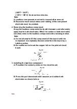


3. Holes on Main Cam Gear
A. The EJECT mode Hole on Main Cam Gear should be a Through
Hole with Hole A on Support Angle in EJECT mode. The each
mode Hole on Main Cam Gear should be a Through Hole with
Hole B on SupportAngle in each mode.
Fig. J3-5
4. Main Cam Gear Kit
A. Main Cam Gear is supplied as a Main Cam Gear Kit only (Kit
No. VVGS0009).
Main Cam Gear Kit consists of a Main Cam Gear and a Main
Cam Push Nut.
However, Main Cam Push Nut is available separately as a
replacement part.
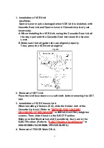
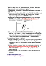
5. Installation of Main Cam Gear and Main Cam Push Nut
A. After installing the Support Angle, install the Main Cam Push
Nut with Needlenose Pliers etc. so that it is flush with the
chassis.
There may be some slight scratches on the Shaft of Main Cam
Gear, when removing the Main Cam Gear. In case that the Main
Cam Gear can be installed securely without tottering, it is fine
to use the one. If any tottering, installall new parts.
Fig. J3-6
35
Summary of Contents for OmniVision PV-C2780-K
Page 8: ...Fig 1 3 Fig 1 4 8 ...
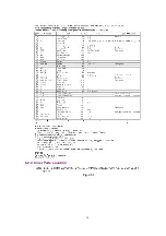
Page 26: ...Fig D5 6 1 2 1 Notes in chart 26 ...
Page 29: ...6 2 2 Inner Parts Location Fig J1 1 29 ...
Page 30: ...6 2 3 EJECT Position Confirmation Fig J1 2 30 ...
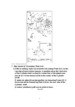
Page 31: ...6 2 4 Grounding Plate Unit Full Erase Head and Cylinder Unit Fig J2 1 31 ...
Page 44: ...6 3 CASSETTE UP ASS Y SECTION 6 3 1 Top Plate Wiper Arm Unit and Holder Unit Fig K1 1 44 ...
Page 81: ...81 ...
Page 85: ...11 2 MECHANISM BOTTOM SECTION 85 ...
Page 86: ...11 3 CASSETTE UP COMPARTMENT SECTION 86 ...
Page 87: ...11 4 CHASSIS FRAME SECTION 1 87 ...
Page 88: ...11 5 CHASSIS FRAME SECTION 2 88 ...
Page 89: ...11 6 PACKING PARTS AND ACCESSORIES SECTION 89 ...