


Note:
Old type of H-Position Adjustment Driver (VFK0136) can be used for
this adjustment.
7.3. ELECTRICAL ADJUSTMENT
NOTE:
Following Adjustments have been preadjusted at factory and are not required.
- Purity Adjustment
- Static Central Convergence Adjustment
- Dynamic Convergence Adjustment
7.3.1. TEST EQUIPMENT
To do all of these electrical adjustments, the following equipment is required.
1. Dual-Trace Oscilloscope
Voltage Range: 0.001 V to 50 V/Div.
Frequency Range: DC to 50 MHz
Probes: 10:1, 1:1
2. NTSC Video Pattern Generator
3. DVM (Digital Volt Meter)
4. MTS/SAP Signal Generator
(TV Multi-Channel Sound Modulator (U.S.A.))
5. Frequency Counter
Frequency Range: 0 to 150 MHz
6. Plastic Tip Driver and Non-Metal Driver
7. Isolation Transformer (Variable)
8. VHS Alignment Tape (VFMS0003H6)
9. Degaussing Coil
10. White Pattern Generator
11. Audio Generator
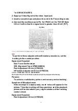
7.3.2. HOW TO READ THE ADJUSTMENT PROCEDURES
Fig. E1
56
Summary of Contents for OmniVision PV-C2780-K
Page 8: ...Fig 1 3 Fig 1 4 8 ...
Page 26: ...Fig D5 6 1 2 1 Notes in chart 26 ...
Page 29: ...6 2 2 Inner Parts Location Fig J1 1 29 ...
Page 30: ...6 2 3 EJECT Position Confirmation Fig J1 2 30 ...
Page 31: ...6 2 4 Grounding Plate Unit Full Erase Head and Cylinder Unit Fig J2 1 31 ...
Page 44: ...6 3 CASSETTE UP ASS Y SECTION 6 3 1 Top Plate Wiper Arm Unit and Holder Unit Fig K1 1 44 ...
Page 81: ...81 ...
Page 85: ...11 2 MECHANISM BOTTOM SECTION 85 ...
Page 86: ...11 3 CASSETTE UP COMPARTMENT SECTION 86 ...
Page 87: ...11 4 CHASSIS FRAME SECTION 1 87 ...
Page 88: ...11 5 CHASSIS FRAME SECTION 2 88 ...
Page 89: ...11 6 PACKING PARTS AND ACCESSORIES SECTION 89 ...