To set the standard color phase.
Symptom of Misadjustment :
Color phase will be shifted.
Test Point:
Pin 5 of P8001 (TV PROCESS C.B.A.)
or TP49 (CRT C.B.A.)
Adjustment:
SUB COLOR (EVR),
SUB TINT (EVR),
R-SUB COLOR (EVR),
R-SUB TINT (EVR)
Specification:
C= 1.50 V[p-p]±0.15 V[p-p]
Input:
Antenna Input Terminal,
Rainbow Color Bar
Mode:
STOP
Equipment:
Oscilloscope,
NTSC Video Pattern Generator
1. Set to PINP mode, and then set PARENT PICTURE to UHF/VHF
TUNER/TV DEMODULATOR 2 UNIT input.
2. Supply the Rainbow Color Bar signal to Antenna Input Terminal.
3. Select SUB BRIGHT in EVR adjustment mode. Then, after making
a note of the original value, adjust to the minimum (C0).
4. Connect the Oscilloscope to Pin 5 of P8001 on the TV PROCESS
C.B.A. or TP49 on the CRT C.B.A.
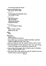
5. Select SUB TINT in EVR adjustment mode and adjust so that level
A and B should be equal in amplitude.
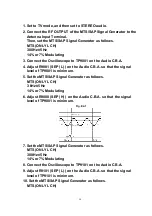
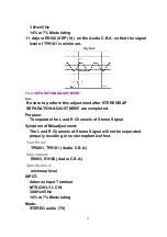
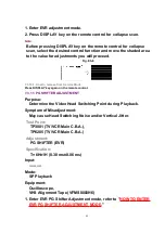
Fig. E9-1
71
Summary of Contents for OmniVision PV-C2780-K
Page 8: ...Fig 1 3 Fig 1 4 8 ...
Page 26: ...Fig D5 6 1 2 1 Notes in chart 26 ...
Page 29: ...6 2 2 Inner Parts Location Fig J1 1 29 ...
Page 30: ...6 2 3 EJECT Position Confirmation Fig J1 2 30 ...
Page 31: ...6 2 4 Grounding Plate Unit Full Erase Head and Cylinder Unit Fig J2 1 31 ...
Page 44: ...6 3 CASSETTE UP ASS Y SECTION 6 3 1 Top Plate Wiper Arm Unit and Holder Unit Fig K1 1 44 ...
Page 81: ...81 ...
Page 85: ...11 2 MECHANISM BOTTOM SECTION 85 ...
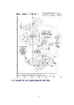
Page 86: ...11 3 CASSETTE UP COMPARTMENT SECTION 86 ...
Page 87: ...11 4 CHASSIS FRAME SECTION 1 87 ...
Page 88: ...11 5 CHASSIS FRAME SECTION 2 88 ...
Page 89: ...11 6 PACKING PARTS AND ACCESSORIES SECTION 89 ...


