


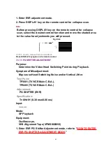


6. Select SUB COLOR in EVR adjustment mode and adjust so that
the level C is 1.50 V[p-p]±0.15 V[p-p].
Fig. E9-2
7. Select SUB BRIGHT in EVR adjustment mode and reset to the
original value.
8. Set PARENT PICTURE to UHF/VHF TUNER/TV DEMODULATOR 1
UNIT input.
9. Select R-SUB BRIGHT in EVR adjustment mode. Then, after
making a note of the original value, adjust to the minimum (C0).
10. Select R-SUB TINT in EVR adjustment mode and adjust so that
level A and B should be equal in amplitude.
11. Select R-SUB COLOR in EVR adjustment mode and adjust so
that the level C is 1.50 V[p-p]±0.15 V[p-p].
7.3.15. V. HEIGHT/H. POSITION ADJUSTMENT
Purpose :
72
Summary of Contents for OmniVision PV-C2780-K
Page 8: ...Fig 1 3 Fig 1 4 8 ...
Page 26: ...Fig D5 6 1 2 1 Notes in chart 26 ...
Page 29: ...6 2 2 Inner Parts Location Fig J1 1 29 ...
Page 30: ...6 2 3 EJECT Position Confirmation Fig J1 2 30 ...
Page 31: ...6 2 4 Grounding Plate Unit Full Erase Head and Cylinder Unit Fig J2 1 31 ...
Page 44: ...6 3 CASSETTE UP ASS Y SECTION 6 3 1 Top Plate Wiper Arm Unit and Holder Unit Fig K1 1 44 ...
Page 81: ...81 ...
Page 85: ...11 2 MECHANISM BOTTOM SECTION 85 ...
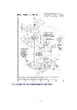
Page 86: ...11 3 CASSETTE UP COMPARTMENT SECTION 86 ...
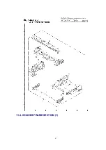
Page 87: ...11 4 CHASSIS FRAME SECTION 1 87 ...
Page 88: ...11 5 CHASSIS FRAME SECTION 2 88 ...
Page 89: ...11 6 PACKING PARTS AND ACCESSORIES SECTION 89 ...