


22. Turn the SCREEN CONTROL on the Flyback Transformer
clockwise carefully and stop at the point where any color is first
observed.
23. In EVR adjustment mode, select the two colors not observed in
step 22 from the following control functions (B CUT -OFF, G CUT -
OFF, or R CUT -OFF) and adjust so that the horizontal line
becomes white.
For example, if the horizontal line appeared red in step 22, select
and adjust the B CUT -OFF and G CUT -OFF.
24. Supply a White Pattern Signal to the Antenna Input Terminal.
25. Press DISPLAY key on the remote control again to return for full
frame scan.
26. Select G DRIVE and B DRIVE in EVR adjustment mode and
adjust so that the entire screen is white.
27. Select R-SUB BRIGHT in EVR adjustment mode. Then, after
making a note of the original value, adjust to the minimum (C0)
and while turning SUB BRIGHT value from minimum (C0) up to
maximum (3F), confirm thatthe screen is tracking the White
Pattern properly. Repeat the above steps 19, 23, 25, and 26 until
the screen is properly tracking the White Pattern.
Note:
Before pressing DISPLAY key on the remote control for collapse
scan, select the desired control function and move the shaded area
to the value.
7.3.17. SUB BRIGHTNESS ADJUSTMENT
Purpose :
To set the optimum brightness level.
Symptom of Misadjustment :
The picture is too white or too black.
Note:
Perform this adjustment in a darkened room.
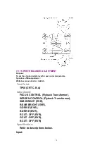
Test Point:
----------
77
Summary of Contents for OmniVision PV-C2780-K
Page 8: ...Fig 1 3 Fig 1 4 8 ...
Page 26: ...Fig D5 6 1 2 1 Notes in chart 26 ...
Page 29: ...6 2 2 Inner Parts Location Fig J1 1 29 ...
Page 30: ...6 2 3 EJECT Position Confirmation Fig J1 2 30 ...
Page 31: ...6 2 4 Grounding Plate Unit Full Erase Head and Cylinder Unit Fig J2 1 31 ...
Page 44: ...6 3 CASSETTE UP ASS Y SECTION 6 3 1 Top Plate Wiper Arm Unit and Holder Unit Fig K1 1 44 ...
Page 81: ...81 ...
Page 85: ...11 2 MECHANISM BOTTOM SECTION 85 ...
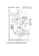
Page 86: ...11 3 CASSETTE UP COMPARTMENT SECTION 86 ...
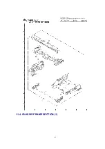
Page 87: ...11 4 CHASSIS FRAME SECTION 1 87 ...
Page 88: ...11 5 CHASSIS FRAME SECTION 2 88 ...
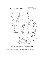
Page 89: ...11 6 PACKING PARTS AND ACCESSORIES SECTION 89 ...