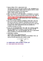
7. Capstan Stator C.B.A. replacement note:
The following parts on the Capstan Stator C.B.A. (VEMS0331) are
not supplied separately. Please order and replace with the circuit
board assembly instead of individual parts.
(Q2501, Q2502, Q2503, Capstan Coil)
8. When installing the IC2501 (AN3846SC or AN3845SC) or Capstan
Stator C.B.A., be sure to apply Silicon Grease (VFK1301). Refer to
"
Stopper Angle, Capstan RotorUnit, Oil Seal, Capstan Stator
C.B.A., and MR Head
" of MECHANISM SECTION in DISASSEMBLY/
ASSEMBLY PROCEDURES.
9. Since the UHF/VHF TUNER/TV DEMODULATOR UNIT 1 (Ref. No.
E21) and the UHF/VHF TUNER/TV DEMODULATOR UNIT 2 (Ref.
No. E150) have already been pre-adjusted at the factory, donot try
to adjust them. Their replacement parts are available as a
complete assembly unit only.
10. Since the FM TRANSMITTER C.B.A. (Ref. No. E139) has already
been pre-adjusted at the factory, do not try to adjust the FM
TRANSMITTER C.B.A. The FM TRANSMITTER C.B.A. replacement
part is available as a completeassembly unit only.
11. EEPROM IC (IC6004),
TV/VCR Main C.B.A. replacement note:
When replacing EEPROM IC (IC6004) or TV/VCR Main C.B.A., be
sure to write the initial data with remote control.
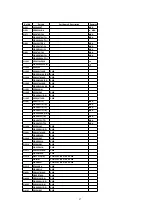
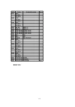
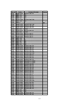
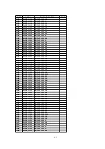
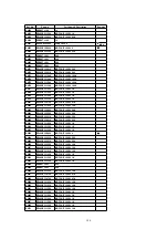
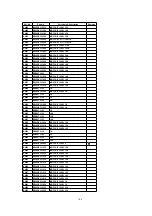
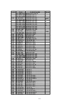
12.2. MECHANICAL REPLACEMENT PARTS LIST
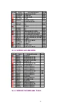
12.2.1. MECHANISM PARTS ON CHASSIS
93
Summary of Contents for OmniVision PV-C2780-K
Page 8: ...Fig 1 3 Fig 1 4 8 ...
Page 26: ...Fig D5 6 1 2 1 Notes in chart 26 ...
Page 29: ...6 2 2 Inner Parts Location Fig J1 1 29 ...
Page 30: ...6 2 3 EJECT Position Confirmation Fig J1 2 30 ...
Page 31: ...6 2 4 Grounding Plate Unit Full Erase Head and Cylinder Unit Fig J2 1 31 ...
Page 44: ...6 3 CASSETTE UP ASS Y SECTION 6 3 1 Top Plate Wiper Arm Unit and Holder Unit Fig K1 1 44 ...
Page 81: ...81 ...
Page 85: ...11 2 MECHANISM BOTTOM SECTION 85 ...
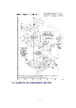
Page 86: ...11 3 CASSETTE UP COMPARTMENT SECTION 86 ...
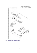
Page 87: ...11 4 CHASSIS FRAME SECTION 1 87 ...
Page 88: ...11 5 CHASSIS FRAME SECTION 2 88 ...
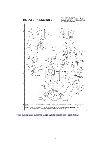
Page 89: ...11 6 PACKING PARTS AND ACCESSORIES SECTION 89 ...


