2-13
VFKS0010
P2
P3
P5
Fig. M10-1
3. Then measure the top portion of the Reel Table and
compare the difference against the result of the
measurement taken in the above step. Do the same for the
other reel table.
Fig. M10-2
4. If the difference is more than 0.1mm (higher or lower), adjust
the height of the reel table to obtain the specified height.
5. For adjustment, change the poly washer located under the
reel table. (The washer is available in only one size of
0.13mm thick.) Move the locking tab to remove the reel
table.
6. Reinstall the Cassette Up Ass'y and the cabinet parts.
HEIGHT ADJUSTMENT OF TAPE GUIDE
POSTS (PRELIMINARY ADJUSTMENT)
*Equipment Required :
Lock Screw Wrench .................................. (VFKS0032)
Post Adjustment Plate .............................. (VFKS0010)
Reel Table Height Fixture ......................... (VFKS0009)
Post Adjustment Screwdriver ...................... (VFK0329)
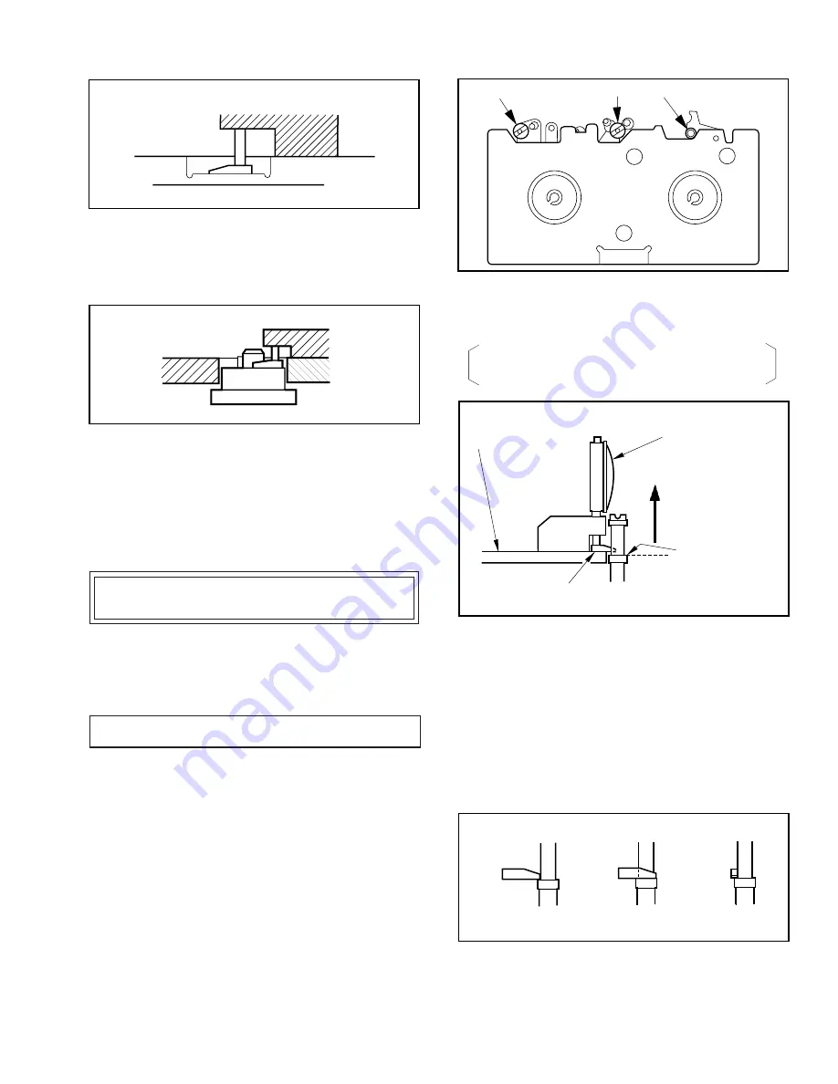
1. HEIGHT ADJUSTMENT OF P2 AND P3
Purpose :
To properly align the position of the tape with the Cylinder
Lead so that the tape runs with stability.
Symptom of Misadjustment :
1) Since the Envelope Waveform Signal cannot be tracked
properly, the Playback picture will be poor.
2) Since the tape does not run smoothly, the tape will
eventually be damaged.
3) Tape interchangeability is poor.
1. Remove the Cassette Up Ass'y.
Then install the Post Adjustment Plate.
VFKS0009
VFKS0010
VFKS0009
VFKS0010
Reel Table
Fig. M11-1
2. First, lower all posts to match the height condition as
shown in Fig. M11-2.
The upper edge of the lower tape guide on each post
should be below the bottom of the foot.
Fig. M11-2
3. Place the fixture on the Post Adjustment Plate and fit the foot
to the Adjustment Plate as shown in Fig. M11-2.
(The foot of the fixture should be fully lowered until it
touches the plate.)
4. Set the fixture to zero (“0”) and slowly raise the post until it
just touches the foot.
When the foot touches the post, it should fit as shown in
Fig. M11-3 (b).
For adjustment of P2 and P3, use a Post Adjustment
Screwdriver.
Fig. M11-3
(Post Adjustment Plate)
VFKS0010
VFKS0009
(Fixture)
First Lower
Then Raise Post
Upper Edge of
Lower Tape Guide
Foot
Post
Side View
Back View
Foot
NO GOOD
GOOD
(a)
(b)
Summary of Contents for OmniVision PV-M1326
Page 42: ......
Page 43: ......
Page 44: ......
Page 45: ......
Page 46: ......
Page 47: ......
Page 48: ......
Page 49: ......
Page 50: ......
Page 51: ......
Page 52: ......
Page 53: ......
Page 54: ......
Page 55: ......
Page 56: ......
Page 57: ......
Page 58: ......
Page 59: ......
Page 60: ......
Page 61: ......
Page 62: ......
Page 63: ......
Page 64: ......
Page 65: ......
Page 66: ......
Page 67: ......
Page 68: ......
Page 69: ......
Page 70: ......
Page 71: ......
Page 72: ......
Page 73: ......
Page 74: ......
Page 75: ......
Page 76: ......
Page 77: ......
Page 78: ......
Page 79: ......
Page 80: ......
Page 81: ......
Page 82: ......
Page 83: ......
Page 84: ......
Page 85: ......
Page 86: ......
Page 87: ......
Page 88: ......
Page 89: ......
Page 90: ......
Page 91: ......
Page 92: ......
Page 93: ......
Page 94: ......
Page 95: ......
Page 96: ......
Page 97: ......
Page 98: ......
Page 99: ......
Page 100: ......
Page 101: ......
Page 102: ......
Page 103: ......
Page 104: ......
Page 105: ......
Page 106: ......
Page 140: ......
Page 141: ......
Page 142: ......
Page 143: ......
Page 144: ......
Page 145: ......
Page 146: ......
Page 147: ......
Page 148: ......
Page 149: ......
Page 150: ......
Page 151: ......
Page 152: ......
Page 153: ......
Page 154: ......
Page 155: ......
Page 156: ......
Page 157: ......
Page 158: ......
Page 159: ......
Page 160: ......
Page 161: ......
Page 162: ......
Page 163: ......
Page 164: ......
Page 165: ......
Page 166: ......
Page 167: ......
Page 168: ......
Page 169: ......
Page 170: ......
Page 171: ......
Page 172: ......
Page 173: ...Printed in Japan R...


