2-17
2-18
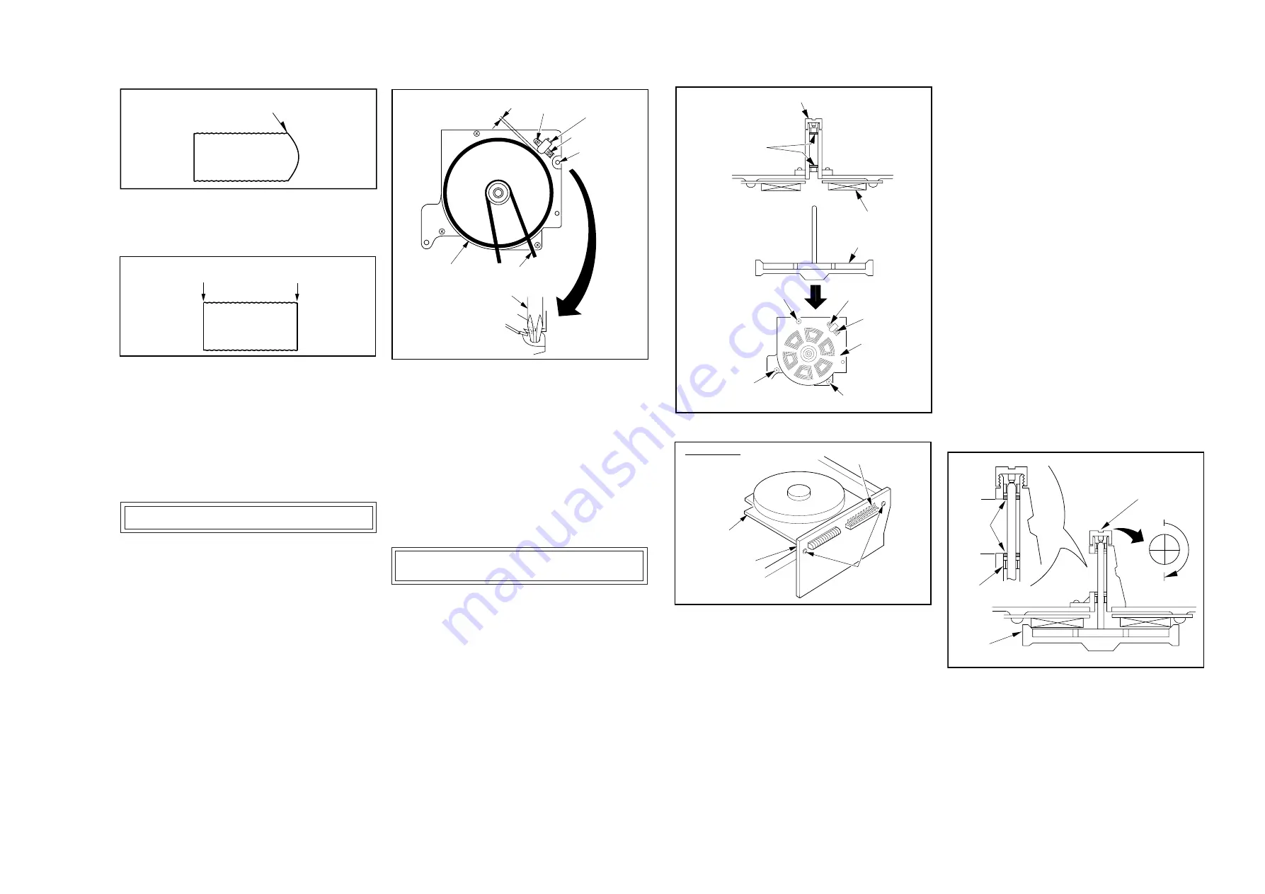
Screw (B)
Hole (C)
FG Head
Capstan Belt
Capstan Rotor
Unit
0.13 ± 0.02mm
Screwdriver
Black Screw (A)
Fig. M17-3
5. When P2 and P3 are adjusted properly, there is no
Envelope Drop at the beginning or end of the track as
shown in Fig. M17-4.
Fig. M17-4
6. Remove a jumper between TP6003 and +5V(TP6020).
Note:
Upon completion of the adjustment of P2 and P3, confirm
the Horizontal Position of the A/C Head by pushing the
Tracking Control Up or Down Buttons alternately, using
the Infrared Remote Control Unit, to check the symmetry
of the envelope. If required, perform “HORIZONTAL
POSITION ADJUSTMENT OF A/C HEAD,” Page 2-16.
ADJUSTMENT OF FG HEAD GAP
Purpose :
To properly pick up the FG Signal.
Symptom of Misadjustment :
If the FG Signal is not properly picked up, Servo Operation
cannot be achieved.
* Equipment Required :
Oscilloscope
* Specification : ........................................... 0.13
±
0.02mm
1. Remove the VCR Chassis Unit and then place it upside
down.
2. Remove the VCR Main C.B.A..
3. Slightly loosen Black Screw (A) and Screw (B). Then set the
Screwdriver (#1 or #2 Phillips Driver) into the Hole (C)
shown in Fig. M18. Turn the screwdriver counterclockwise
until the FG Head touches the rotor. Then turn it slightly
clockwise to the clearance as specified.
4. Tighten Black Screw (A) and Screw (B) shown in Fig. M18.
5. Reinstall the VCR Main C.B.A.Fig. M18
Dropping envelope level at
the end of track (P3)
Envelope Is Adjusted Properly
(No Envelope Drop)
Fig. M18
Note :
Do not touch the outside circumference of the rotor
surface with any tool and keep magnetic material away
from the rotor magnet (especially metal particles).
(Confirmation)
1) Supply a Video Signal to the Video Input Jack on the rear
side of the deck.
2) Insert a cassette tape and place the unit in SLP recording
mode.
3) Connect the oscilloscope to Pin 15 of P2502 on the Capstan
Motor Drive C.B.A..
Confirm that the signal level is greater than 10mVp-p.
REPLACEMENT OF CAPSTAN ROTOR
OR STATOR UNIT
1. Remove the Capstan Belt (Fig. M18).
2. In the order described in the Disassembly and Assembly
Procedures of Mechanism section, remove the Motor Block
Ass'y.
3. Carefully pull out the Capstan Rotor Unit. Be careful not to
lose the 2 Oil Seals shown in Fig. M19.
P2502
Bottom View
Screws (E)
Capstan Stator Unit
Capstan Motor
Drive C.B.A.
Thrust Adjust Screw
Oil Seals
Coil
CAPSTAN STATOR
CAPSTAN ROTOR
Magnet
Screw (D)
Capstan
Stator Unit
Screw (D)
Screw (B)
Screw (D)
Black
Screw (A)
Caution Note :
1) The replacement Capstan Rotor Unit is available only
as a complete unit with a spring loaded Capstan
Pulley.
2) Hold the new Capstan Rotor Unit firmly when installing
it, so the rotor will not be pulled toward the stator too
quickly (due to magnetic force). Placing some paper
on the coils before rotor installation may prevent
accidental damage to the coils if the above caution is
not observed.
3) During installation, do not touch the Capstan Shaft
with any hard material like drivers or tweezers.
9. Re-install the Capstan Motor Drive C.B.A. by tightening 2
Screws (E). Then carefully solder P2502 and re-install the
Motor Block Ass’y.
ADJUSTMENT OF THRUST ADJUST SCREW
AND OIL SEALS
10. Re-install the Capstan Belt and, while exerting pressure
to turn the Clutch Unit, tighten the Thrust Adjust Screw
slowly until the Capstan Rotor just starts turning.
11. At the point where the Capstan Rotor starts turning,
tighten the Thrust Adjust Screw another 180
°
clockwise.
12. Upon completion of the above procedure, confirm that the
Oil Seals are positioned as shown in Fig. M21 and make
sure that the oil seal does not contact the Pressure
Roller or P5 Arm Unit. Then, wipe off the Capstan
Shaft to remove oil, grease, and dust.
Note :
Clean the Capstan Post whenever an Oil Seal is
moved.
Fig. M21
Fig. M19
Fig. M20.
4. Carefully unsolder P2502 on the Capstan Motor Drive
C.B.A.. Then remove the Capstan Motor Drive C.B.A.
by removing 2 Screws (E) shown in Fig. M20.
5. Remove 3 Screws (D), Black Screw (A) and Screw (B).
Then lift out the Capstan Stator Unit.
6. Install the new Capstan Stator Unit and then tighten 3
Screws (D), Black Screw (A) and Screw (B).
7. Before installing the new Capstan Rotor Unit, loosen the
Thrust Adjust Screw completely.
8. Install the new Capstan Rotor, carefully inserting the
Oil Seals as shown in Fig. M19.
Thrust Adjust Screw
180°
0°
equal
Oil
Seals
Rotor
Bushing
equal
Summary of Contents for OmniVision PV-M1326
Page 42: ......
Page 43: ......
Page 44: ......
Page 45: ......
Page 46: ......
Page 47: ......
Page 48: ......
Page 49: ......
Page 50: ......
Page 51: ......
Page 52: ......
Page 53: ......
Page 54: ......
Page 55: ......
Page 56: ......
Page 57: ......
Page 58: ......
Page 59: ......
Page 60: ......
Page 61: ......
Page 62: ......
Page 63: ......
Page 64: ......
Page 65: ......
Page 66: ......
Page 67: ......
Page 68: ......
Page 69: ......
Page 70: ......
Page 71: ......
Page 72: ......
Page 73: ......
Page 74: ......
Page 75: ......
Page 76: ......
Page 77: ......
Page 78: ......
Page 79: ......
Page 80: ......
Page 81: ......
Page 82: ......
Page 83: ......
Page 84: ......
Page 85: ......
Page 86: ......
Page 87: ......
Page 88: ......
Page 89: ......
Page 90: ......
Page 91: ......
Page 92: ......
Page 93: ......
Page 94: ......
Page 95: ......
Page 96: ......
Page 97: ......
Page 98: ......
Page 99: ......
Page 100: ......
Page 101: ......
Page 102: ......
Page 103: ......
Page 104: ......
Page 105: ......
Page 106: ......
Page 140: ......
Page 141: ......
Page 142: ......
Page 143: ......
Page 144: ......
Page 145: ......
Page 146: ......
Page 147: ......
Page 148: ......
Page 149: ......
Page 150: ......
Page 151: ......
Page 152: ......
Page 153: ......
Page 154: ......
Page 155: ......
Page 156: ......
Page 157: ......
Page 158: ......
Page 159: ......
Page 160: ......
Page 161: ......
Page 162: ......
Page 163: ......
Page 164: ......
Page 165: ......
Page 166: ......
Page 167: ......
Page 168: ......
Page 169: ......
Page 170: ......
Page 171: ......
Page 172: ......
Page 173: ...Printed in Japan R...


