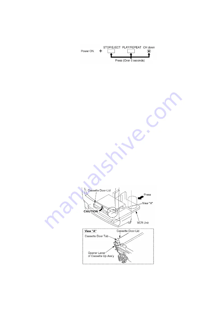
over 5 seconds in power on condition.
Fig. 3
The unit goes into service mode.
In this mode, Mechanism movement can be confirmed. When removing Cassette Up Ass’y, it can
be confirmed without a cassette.
To release from this mode, press POWER button off or disconnect AC Plug.
5.1.6. DEFEATING THE AUTO TRACKING
To defeat the Auto Tracking Function, place the instrument in the STOP mode and place a jumper
between TP6003 and TP6009 on the TV/VCR Main C.B.A. The tracking will be placed in the neutral
position.
5.1.7. CAUTION FOR INSTALLATION OF VCR UNIT
CAUTION:
Opener Lever may be damaged when VCR Unit is installed, with
Cassette Door-Lid and Opener Lever of Cassette Up Ass’y set
incorrectly.
Install the VCR Unit as follows:
1. Swing the Cassette Door-Lid all the way open until the Cassette
Door tab clears the Opener Lever.
2. Make sure that all guide tabs are aligned properly. Then, press the
VCR Unit straight in.
Fig. 4
5.1.8. HOW TO INITIALIZE MEMORY IC
After the Memory IC (IC6004) or TV/VCR Main C.B.A. is replaced, be sure to set the Default value
to Memory IC as shown in "Memory IC Reference Table" below.
13
Summary of Contents for OmniVision PV-Q1311
Page 9: ...Fig 1 4 Fig 1 5 9...
Page 23: ...5 2 IC TRANSISTOR AND CHIP PART INFORMATION 23...
Page 27: ...Fig D4 Fig D5 27...
Page 31: ...6 2 2 Inner Parts Location Fig J1 1 31...
Page 32: ...6 2 3 EJECT Position Confirmation Fig J1 2 32...
Page 33: ...6 2 4 Grounding Plate Unit Full Erase Head and Cylinder Unit Fig J2 1 33...
Page 84: ...84...
Page 88: ...11 2 MECHANISM BOTTOM SECTION 88...
Page 89: ...11 3 CASSETTE UP COMPARTMENT SECTION 89...
Page 90: ...11 4 CHASSIS FRAME SECTION 1 90...
Page 91: ...11 5 CHASSIS FRAME SECTION 2 91...
Page 93: ...Model PV C2011 PV C2021 PV C2031W VV 2001 PV C2061 93...
Page 111: ...R4591 ERDS2TJ681T CARBON 1 4W 680 111...
Page 113: ...R6009 ERJ6GEYJ102V MGF CHIP 1 10W 1K 113...
Page 135: ...R6032 ERJ6GEYJ102V MGF CHIP 1 10W 1K 135...


