19
TV Operation
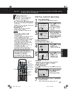
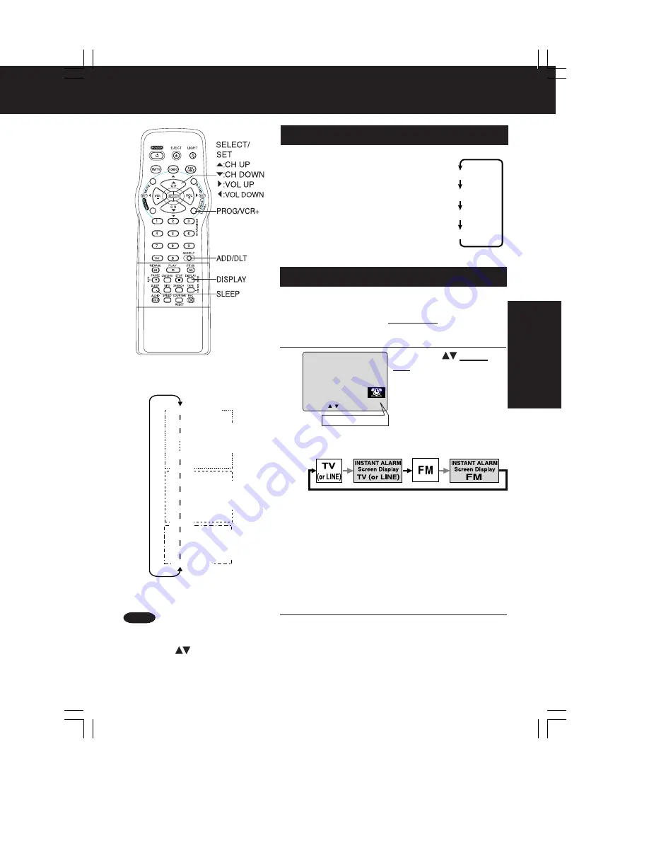
Press SLEEP repeatedly
to set SLEEP TIMER.
• Pressing DISPLAY with
sleep timer set displays
remaining time.
Press SLEEP repeatedly
until “SLEEP TIMER 00”
appears to cancel.
SLEEP TIMER
This unit can be set for auto power off.
INSTANT ALARM
You can set a timer alarm up to 60 min. Useful when
you are cooking, etc.
1
2
3
To cancel, press TIMER/FM then press ADD/DLT on
the remote while CANCEL/SET screen is displayed.
To increase timer in progress, repeat step 2. Time
will be rounded up to next 1, 5, or 10 minute interval.
(See chart left.)
<Example>
• If current time remaining is 12:15, countdown will
restart from 15:00.
• If current time remaining is 9:15, countdown will restart
from 10:00.
Press CH
on the
unit with CANCEL/SET
screen displayed to set
alarm.
(Time changes in
the order shown left.)
Alarm will sound at 0: 00.
Press any button to stop
• The volume of the alarm gradually increases for
one minute and then continues to beep until
any button is pressed.
• Pressing TIMER/FM repeatedly on the unit
will change display as follows.
List
orrect time.
SLEEP TIMER 30
SLEEP TIMER 60
SLEEP TIMER 90
SLEEP TIMER 00
Press TIMER/FM on the unit to display
the instant alarm CANCEL/SET screen.
Remaining Time
5 : 20PM
CANCEL : ADD / DLT 02 : 00
SET : CH KEY ON UN I T
While timer function is in progress,
you can change channels on the
unit with CH
while “CANCEL/
SET” screen is not displayed.
Note
*Important:
if a remote control button does not work when pressed, press the COMBO button
on the remote and try the button again.
1:00 (one minute)
2:00
3:00
9:00
10:00
15:00
20:00
25:00
30:00
40:00
50:00
60:00 (Max)
one-minute
increase
until 10:00
five-minute
increase
until 30:00
ten-minute
increase
until 60:00
C2061- P18-19 TV Timer
00.12.14, 5:33 PM
19
Summary of Contents for OmniVision PV-Q1311
Page 9: ...Fig 1 4 Fig 1 5 9...
Page 23: ...5 2 IC TRANSISTOR AND CHIP PART INFORMATION 23...
Page 27: ...Fig D4 Fig D5 27...
Page 31: ...6 2 2 Inner Parts Location Fig J1 1 31...
Page 32: ...6 2 3 EJECT Position Confirmation Fig J1 2 32...
Page 33: ...6 2 4 Grounding Plate Unit Full Erase Head and Cylinder Unit Fig J2 1 33...
Page 84: ...84...
Page 88: ...11 2 MECHANISM BOTTOM SECTION 88...
Page 89: ...11 3 CASSETTE UP COMPARTMENT SECTION 89...
Page 90: ...11 4 CHASSIS FRAME SECTION 1 90...
Page 91: ...11 5 CHASSIS FRAME SECTION 2 91...
Page 93: ...Model PV C2011 PV C2021 PV C2031W VV 2001 PV C2061 93...
Page 111: ...R4591 ERDS2TJ681T CARBON 1 4W 680 111...
Page 113: ...R6009 ERJ6GEYJ102V MGF CHIP 1 10W 1K 113...
Page 135: ...R6032 ERJ6GEYJ102V MGF CHIP 1 10W 1K 135...


