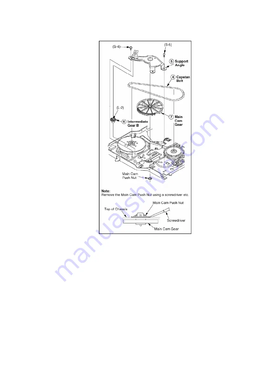
6.2.5.1. Reassembly Notes
1. Alignment of Main Cam Gear, Drive Rack Arm, and Main Rod
A. Confirm that the hole on Main Rod is a Through Hole with a hole
on chassis.
B. Confirm that the hole on Drive Rack Arm is a Through Hole with
a hole on chassis.
C. Install the Main Cam Gear so that the projection of Main Cam
Gear is in the upward position as shown.
Fig. J3-2
36
Summary of Contents for OmniVision PV-Q1311
Page 9: ...Fig 1 4 Fig 1 5 9...
Page 23: ...5 2 IC TRANSISTOR AND CHIP PART INFORMATION 23...
Page 27: ...Fig D4 Fig D5 27...
Page 31: ...6 2 2 Inner Parts Location Fig J1 1 31...
Page 32: ...6 2 3 EJECT Position Confirmation Fig J1 2 32...
Page 33: ...6 2 4 Grounding Plate Unit Full Erase Head and Cylinder Unit Fig J2 1 33...
Page 84: ...84...
Page 88: ...11 2 MECHANISM BOTTOM SECTION 88...
Page 89: ...11 3 CASSETTE UP COMPARTMENT SECTION 89...
Page 90: ...11 4 CHASSIS FRAME SECTION 1 90...
Page 91: ...11 5 CHASSIS FRAME SECTION 2 91...
Page 93: ...Model PV C2011 PV C2021 PV C2031W VV 2001 PV C2061 93...
Page 111: ...R4591 ERDS2TJ681T CARBON 1 4W 680 111...
Page 113: ...R6009 ERJ6GEYJ102V MGF CHIP 1 10W 1K 113...
Page 135: ...R6032 ERJ6GEYJ102V MGF CHIP 1 10W 1K 135...


