23
9 Disassembly and Assembly Instructions
9.1.
Remove the Rear cover
1. See PCB Layout (Section 3)
9.2.
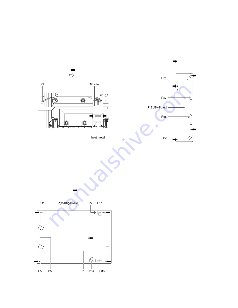
Remove the AC inlet
Caution:
To remove P.C.B. wait 1 minute after power was off for dis-
charge from electrolysis capacitors.
1. Unlock the cable clampers to free the cable.
2. Disconnect the connector (P9).
3. Remove the screws (
×
2
) and remove the Inlet metal.
4. Remove the screw (
×
1
) and remove the AC inlet.
9.3.
Remove the P(MAIN)-Board
Caution:
To remove P.C.B. wait 1 minute after power was off for dis-
charge from electrolysis capacitors.
1. Unlock the cable clampers to free the cable
2. Disconnect the connectors (P52, P56 and P58)
3. Disconnect the connectors (P2, P6, P11 and P35).
4. Disconnect a short-jumper connector P34 and re-use for
new P(MAIN)-Board.
5. Remove the screws (
×
5
) and remove the P(MAIN)-
Board.
9.4.
Remove the P(SUB)-Board
Caution:
To remove P.C.B. wait 1 minute after power was off for dis-
charge from electrolysis capacitors.
1. Unlock the cable clampers to free the cable.
2. Disconnect the connectors (P51, P55 and P57).
3. Disconnect the connector (P9).
4. Remove the screws (
×
4
) and remove the P(SUB)-
Board.
Summary of Contents for P50GT30
Page 20: ...20 7 4 No Picture ...
Page 33: ...33 ...
Page 34: ...34 ...
Page 40: ...40 ...
Page 42: ...42 12 4 Wiring 3 ...
Page 43: ...43 12 5 Wiring 4 ...
Page 44: ...44 12 6 Wiring 5 ...
Page 45: ...45 12 7 Wiring 6 ...
Page 46: ...46 12 8 Wiring 7 ...
Page 47: ...Model No TC P55GT30 Schematic Diagram Note S 1 ...
Page 48: ...Model No TC P55GT30 Replacement Parts List Note S 2 ...
Page 49: ...Model No TC P55GT30 A Board 1 14 S 3 ...
Page 50: ...Model No TC P55GT30 A Board 2 14 S 4 ...
Page 51: ...Model No TC P55GT30 A Board 3 14 S 5 ...
Page 52: ...Model No TC P55GT30 A Board 4 14 S 6 ...
Page 53: ...Model No TC P55GT30 A Board 5 14 S 7 ...
Page 54: ...Model No TC P55GT30 A Board 6 14 S 8 ...
Page 55: ...Model No TC P55GT30 A Board 7 14 S 9 ...
Page 56: ...Model No TC P55GT30 A Board 8 14 S 10 ...
Page 57: ...Model No TC P55GT30 A Board 9 14 S 11 ...
Page 58: ...Model No TC P55GT30 A Board 10 14 S 12 ...
Page 59: ...Model No TC P55GT30 A Board 11 14 S 13 ...
Page 60: ...Model No TC P55GT30 A Board 12 14 S 14 ...
Page 61: ...Model No TC P55GT30 A Board 13 14 S 15 ...
Page 62: ...Model No TC P55GT30 A Board 14 14 S 16 ...
Page 63: ...Model No TC P55GT30 K S and V Board S 17 ...
Page 64: ...Model No TC P55GT30 C1 Board S 18 ...
Page 65: ...Model No TC P55GT30 C2 Board 1 2 S 19 ...
Page 66: ...Model No TC P55GT30 C2 Board 2 2 S 20 ...
Page 67: ...Model No TC P55GT30 C3 Board 1 2 S 21 ...
Page 68: ...Model No TC P55GT30 C3 Board 2 2 S 22 ...
Page 69: ...Model No TC P55GT30 SC Board 1 4 S 23 ...
Page 70: ...Model No TC P55GT30 SC Board 2 4 S 24 ...
Page 71: ...Model No TC P55GT30 SC Board 3 4 S 25 ...
Page 72: ...Model No TC P55GT30 SC Board 4 4 S 26 ...
Page 73: ...Model No TC P55GT30 SS Board 1 2 S 27 ...
Page 74: ...Model No TC P55GT30 SS Board 2 2 and SS2 Board S 28 ...
Page 75: ...Model No TC P55GT30 A Board Foil side S 29 ...
Page 76: ...Model No TC P55GT30 A Board Component side S 30 ...
Page 77: ...Model No TC P55GT30 K S and V Board S 31 ...
Page 78: ...Model No TC P55GT30 C1 Board S 32 ...
Page 79: ...Model No TC P55GT30 C2 Board S 33 ...
Page 80: ...Model No TC P55GT30 C3 Board S 34 ...
Page 81: ...Model No TC P55GT30 SC Board Foil side S 35 ...
Page 82: ...Model No TC P55GT30 SC Board Component side S 36 ...
Page 83: ...Model No TC P55GT30 SS Board Foil side S 37 ...
Page 84: ...Model No TC P55GT30 SS Board Component side S 38 ...
Page 85: ...Model No TC P55GT30 SS2 Board S 39 ...
Page 114: ...Model No TC P55GT30 Exploded View 1 S 68 ...
Page 115: ...Model No TC P55GT30 Exploded View 2 S 69 ...


