background image


Operation manual for Narrow pitch connectors P5K 


Panasonic Corporation
industrial.panasonic.com/ac/e/ 


©

 Panasonic Corporation 2017 

ACCTF29E-1   201708 


- 3 -


02. Precautions for equipment design 

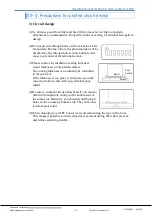
02-1. Precautions for mechanical design 

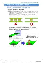
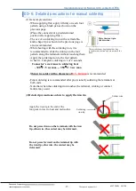
1) Position of connectors on a board 


(1) 

When using board to board connectors, a pair of board shall NOT be connected   

with multiple connectors. Otherwise, misaligned connector positions may  cause   
mating failure or product breakage. 
Panasonic corporation does not guarantee the failures caused by using the 
multiple connectors.


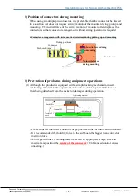
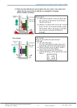
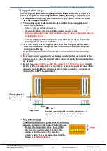
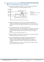
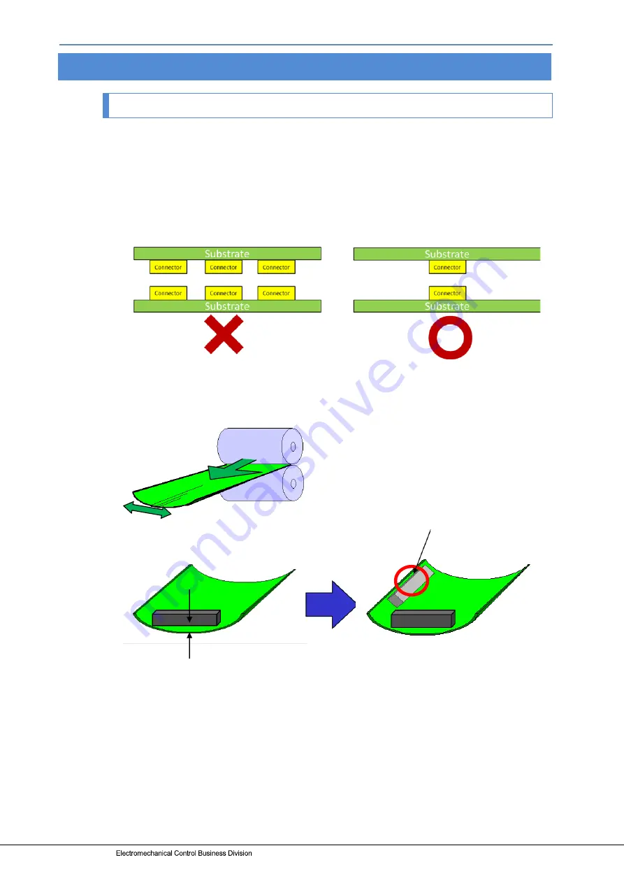
(2)Solid board is tend to warp to vertical direction against mill direction of 
production process. Some warp directions can cause poor soldering. Therefore, 
arrange the board in a direction that can minimize warp.  


This gap causes poor  
soldering.  


Tendency to warp easily to 
production direction (horizontal direction)  

It is possible to prevent poor soldering 
by the arrangement of mounting 
connector on the horizontal direction.  


×

Summary of Contents for P5K

Page 1: ...ACCTF29E 1 2017 08 industrial panasonic com ac e P5K Narrow pitch Connectors onnector Operation manual ...

Page 2: ...tion 2017 ACCTF29E 1 201708 1 Contents 01 Introduction 2 02 Precautions for equipment design 3 03 Precautions during mounting to reflow 13 04 Precautions for mating 19 05 Precautions for facilitate elimination of defective products at inspection process 20 Parts that require special confirmation are bold and underlined ...

Page 3: ...TF29E 1 201708 2 01 Introduction The P5K narrow pitch connector has a terminal pitch of 0 5 mm and stacking height of 3 0 and 3 5mm This connector is designed for parts requiring space reduction Select models best suited to the situation and conditions of use Read this document before designing the equipment and starting production ...

Page 4: ...ned connector positions may cause mating failure or product breakage Panasonic corporation does not guarantee the failures caused by using the multiple connectors 2 Solid board is tend to warp to vertical direction against mill direction of production process Some warp directions can cause poor soldering Therefore arrange the board in a direction that can minimize warp This gap causes poor solderi...

Page 5: ... of problems during equipment operations 1 Although this product is equipped with a simple locking mechanism insert cushioning material in the equipment enclosure in order to prevent the header from being detached from the socket or damaged during operation Please consider that there should be no gap between the enclosure and the board It is recommended that holding force to the sub board be bigge...

Page 6: ...there is no gap between enclosure and sub board A B the sub board strikes against the enclosure Due to the impact of its strike the connector is affected and might be damaged Prevention Please fix the both main and sub board sufficiently 1 Fix the main board Fix the side that has the larger mass and prevent the inertial motion of drop impact 2 Hold with object such as rubber cushion not to move by...

Page 7: ...l cause poor solder at the terminal section 3 Please control the insulation coating thickness resist thickness on the pattern surface The coating thickness can ordinarily be controlled to the µm level If the thickness is too great it will press up on the connector bottom and will cause terminal poor solder 4 Be sure to consult with us beforehand if you want to perform through hole wiring on the bo...

Page 8: ...ge is more likely to occur if a pattern is laid in a line or if the copper foil is applied over the entire FPC board for noise prevention purposes It is difficult to keep FPC flat because FPC is flexible Example of carrier for mounting process Magic resin Daisho Denshi Silicon gum board Mitsubishi Resin Assist carrier ShinEtsu Polymer Co Ltd When mounting connector it is recommended that the usage...

Page 9: ...layer Generally the coverlay thickness is set to about 30 μm including the adhesive If the thickness exceeds 30 μm remove the coverlay under the connector from the design 3 This connector can be used for main board to FPC connection In case that the flexible board is too short excessive load affects the connector and may be shifted out Please design as the flexible board is appropriately slack Con...

Page 10: ...warp during reflow soldering and cause poor soldering It is recommended to cut the material in the direction of the reinforcing fiber 4 In order to achieve greater device thinness methods that use metals such as stainless steel are used for support plates when extremely thin support plates are desired 5 Design the support plates so that the edges are 0 5 1 0 mm or more outside the tips of the foot...

Page 11: ... sure to adjust the amount of solder applied after checking the finish quality in a test run 2 Compared with natural air reflow soldering N2 reflow soldering can reduce oxidization of the melted solder surface This significantly improves the solder wettability Therefore please make sure to apply an appropriate amount of solder 3 Do not apply an excessive amount of solder otherwise solder or flux m...

Page 12: ... board and window size of metal masking Please refer to the latest product specifications when designing your product Product Narrow pitch connector P5K Socket Recommended mounting pattern on PC board Top view Recommended pattern on metal masking window area Recommended pattern on metal masking window area Thickness of metalmasking 120μm Window ratio 69 Thickness of metalmasking 150μm Window ratio...

Page 13: ...pecifications of mounting pattern on PC board and window size of metal masking Product Narrow pitch connector P5K Header Recommended mounting pattern on PC board Top view Thickness of metalmasking 120μm Window ratio 78 Thickness of metalmasking 150μm Window ratio 62 Recommended pattern on metal masking window area Recommended pattern on metal masking window area ...

Page 14: ...nectors Even if you select a high speed mounter please use a multi function head and load control 03 2 Precautions for selecting a pickup nozzle for mounting connectors Select a pickup nozzle with a pickup area that provides a theoretical lift force 10 times greater than the connector s weight Theoretical lifting force gr Vacuum pressure mmHG 760 1 033 Nozzle area cm2 Sample vacuum pressure of mac...

Page 15: ...es the contact section or its periphery it is possible that the amount of solder applied was excessive or that wicking has occurred In this case check the amount of solder applied and the temperature at the connector mounting position Special care is required with an N2 reflow oven 4 Larger front fillets can be achieved by extending the screen opening outward and shifting the solder application po...

Page 16: ...ring solder rework solder should be supplied at and the soldering iron should be applied to the tip of each pattern trace on the PC board in order to minimize contact with the terminals 3 When carrying out manual soldering or solder rework avoid using flux if possible in order to prevent it from rising to the contact section For details see the next page 4 When using flux apply as little as possib...

Page 17: ...t of solder to be applied is recommended e g BON 102F made by Japan Bonkote Co Ltd 2 Selection of soldering iron for lead free solder in particular Recommendation for 0 5 mm narrow pitch connectors Cutter blade shaped iron tip BJ7 KF made by Japan Bonkote Co Ltd Iron tip with a temperature sensor Temperature controllable iron tip In addition it is necessary to check whether or not the displayed ir...

Page 18: ... iron tip on the foot pattern along the terminals without touching them Apply the soldering iron to the foot pattern to heat it Complete soldering in 1 or 2 seconds Connector s resistance to soldering heat 300 C 5 sec max 350 C 3 sec max Thin wire solder with a diameter of 0 3 0 4 mm is recommended Final soldering is recommended after provisionally soldering the terminals at both ends Note that wh...

Page 19: ...ons prepare equipment for cleaning process beginning with boil cleaning ultrasonic cleaning and then vapor cleaning 2 Carefully oversee the cleanliness of the cleaning fluids to make sure that the contact surfaces do not become dirty from the cleaning fluid itself 3 Since some powerful cleaning solutions may dissolve molded components of the connector and wipe off or discolor printed letters we re...

Page 20: ... positioning Please consider the procedure for temporary positioning rather than quick easy mating 2 Slightly move the connector of the sub PC board in the X and Y directions to check that the connector position is correct PC boards do not slide when the mating position is correct 3 Press down on both sides at the same time while holding as best as possible the PC boards in parallel until mating i...

Page 21: ...in the molded component 2 To ensure long insertion removal life periodically perform ion blowing and air dusting to ensure that there are absolutely no foreign particles inside the connector 3 Buckling distortion may occur in the socket contacts if mating is repeatedly forced when not positioned properly If use is continued in this situation scratching may occur on the header post of the product I...

Page 22: ... pitch connectors P5K Panasonic Corporation industrial panasonic com ac e Panasonic Corporation 2017 ACCTF29E 1 201708 21 Amendment history Manual No Date Changes ACCTF29E July 2016 First edition ACCTF29E 1 Augst 2018 Revised P 3 ...

Page 23: ...ACCTF29E 1 201708 2017 ...

Reviews: