


PAN9520 ETU Evaluation Tool
3 PAN9520 ETU
User Guide Rev. 1.0
Page 31 of 35
The related settings are configured by
the “phy_init_data” binary. Panasonic provides two
version of this file (FCC/IC and RED), which can be used for this purpose. For more information
please refer to the “PAN9520 Module Integration Guide”.
Make
sure that a “phy_init” binary is flashed that complies with the regulations to address
“0xF000”.
3.17.3.1 Default Settings in the
“factory_param” Binary
For a convenient usage of the pre-built AT software with the PAN9520 ETU, it is recommended
to replace the file
factory_param.bin
. This configures the default settings for e.g. the pin
assignment. On the PAN9520 ETU, the standard UART1 pins (GPIO 17 to 20) are connected to
the FT232 USB to UART interface. In contrast, the default WROVER
factory.bin
configures
GPIO 21 as pin RX instead of GPIO 18. By flashing an adapted binary, the on-board
USB-to-UART1 interface can be used for controlling the AT software.
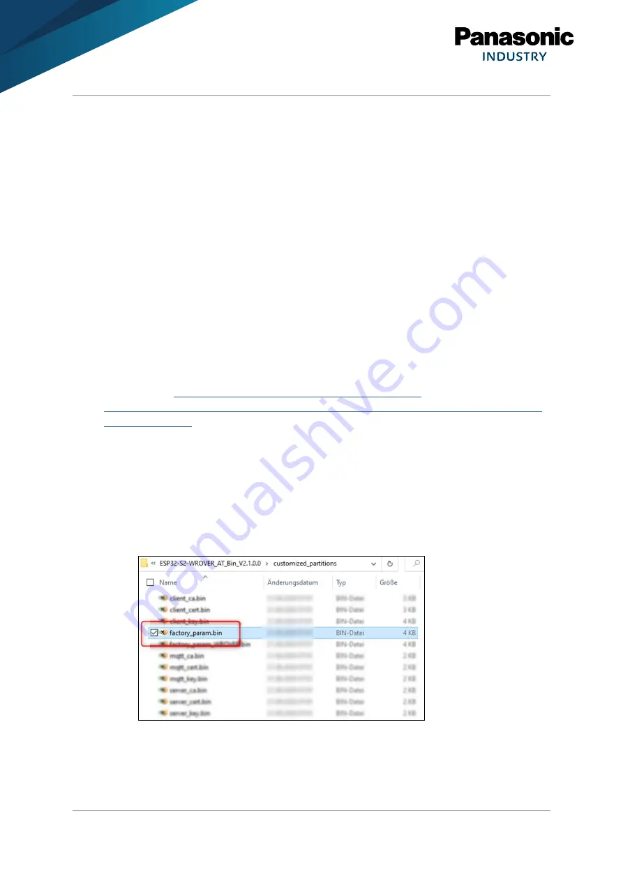
The
“factory_param” binary is located in the folder
ESP32-S2-WROVER_AT_BIN_VX.X.X.X
>
customized_partitions
(AT binary download folder). It is recommended to edit a copy of the
existing binary by using a tool like e.g.
“HxD”.
Other methods are also possible, but require the AT source code to be downloaded (for details
please refer to
https://docs.espressif.com/projects/esp-at/en/release-
Adapting Binary
The following requirement must be met:
✓
A Hex Editor is installed.
In the following the tool “HxD” is used.
1. Navigate to the folder
customized_partitions
.
2. Open either
factory_param.bin
or
factory_param_WROVER.bin
with
HxD
.
3. Optional: Save a copy of the file with a new name.


