background image

13

Opera

ting Instruc

tio

ns

Paper Jams

To release jammed paper:

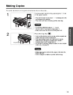
1

Push the door open button and open the printer 
door.

2

Remove the jammed paper by pulling the paper roll 
to the direction A. If the jammed paper is still in the 
cutter cover, remove it using tweezers from slot B.

3

Cut the paper straight as shown in the figure.

4

Pass the paper over the paper feed roller and under 
the cutter cover, then through the output port about 
4 cm  (1

1

/

2

inches). (Refer to step 4 on page 10.)

In case paper cannot go through, just put the paper 
on the paper feed roller and insert the top of the 
paper in the cutter cover as shown in the figure.

5

Close the printer door securely, using two hands.

• Use copy paper roll with a core diameter of 25.4 mm 

(1 inch) or more. Using a copy paper roll with a smaller 
core could cause paper jams.

• Once the door is closed, paper will feed and 

automatically cut. Remove and discard the small piece 
of paper.

PUSH OPEN

Door
Open
Button

Slot B

A

Cutter cover

Cut

Paper feed 
roller

Cutter cover

Notes

UB-5310_MECA.book  13 ページ  2003年5月15日 木曜日 午後5時23分

Summary of Contents for Panaboard UB-5310

Page 1: ...ease refer to the Installation Manual Before operating this unit please read these instructions completely and keep them carefully for future reference This product is designed for installation by a qualified servicing dealer Installation performed by non authorized individuals could cause safety related problems with the operation of this equipment To locate the closest authorized dealer in your ...

Page 2: ...onment This equipment generates uses and can radiate radio frequency energy and if not installed and used in accordance with the instruction manual may cause harmful interference to radio communications Operation of this equipment in a residential area is likely to cause harmful interference in which case the user will be required to correct the interference at his own expense Microsoft Windows an...

Page 3: ...nd Separately available 30 Warning about saving data When the system storage device or any of its optional storage device is adversely effected by operational errors static electricity electrical noise vibration dust or when the power has been cut off due to malfunction repair or inadvertently the memory contents may be lost or changed Before operating the system make a point of reading the precau...

Page 4: ...CING TO QUALIFIED SERVICE PERSONNEL WARNING TO PREVENT FIRE OR SHOCK HAZARD DO NOT EXPOSE THIS PRODUCT TO RAIN OR ANY TYPE OF MOISTURE THE SOCKET OUTLET MUST BE NEAR THIS EQUIPMENT AND MUST BE EASILY ACCESSIBLE The product should be used only with the power cord that is supplied by the manufacturer CLASS 1 LED PRODUCT ...

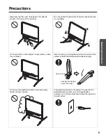
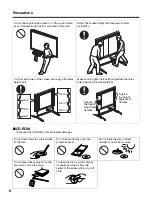
Page 5: ...eavy items on the tray or screen After installing or moving the electronic board lock the casters and set the fall prevention extension legs Do not use the electronic board in an excessively humid or dusty location If the electronic board is not going to be used for an extended period of time e g during extended holidays turn off the power and remove the plug from the wall outlet Locking the caste...

Page 6: ...ighten the height adjustment handles after adjusting the screen height Do not touch or write on the surface of the disc Do not leave the disc out of the protective case Do not leave the disc in direct sunlight or near heat sources Do not place heavy objects on the disc case or drop the case To clean the disc hold the disc by its edges and wipe it from the center to the edges with a dry soft cloth ...

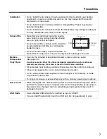
Page 7: ...rasers and Copy Paper Use only the included or designated markers erasers and copy paper See page 30 Use of accessories other than those included or designated such as oil based markers may damage the screen or result in hard to erase markings Store markers horizontally as vertical storage may stop the ink from coming out Store a copy paper roll in a cool dark moisture free location Do not store p...

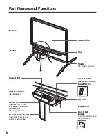
Page 8: ...nter Door Open this door to load copy paper or to remove jammed paper See pages 10 13 Door Open Button Push this button to open the printer door Control Panel See page 9 for details USB Connector See page 16 Stand The stand is optional Scanner Copied Paper Holder This holder holds up to 5 sheets of output paper Printer ...

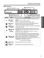
Page 9: ...e Multi Copy Stop Key is pressed Example 1 2 9 1 When an error occurred a flashing symbol will appear in this display to indicate the error status See page 29 Multi Copy Stop Key When making multiple copies press this key until the desired number of copies is displayed on the Multi Copy Error Indicator This key can also be pressed while multiple copies are being made to stop the copying process Th...

Page 10: ...eter of 25 4 mm 1 inch or more Using a copy paper roll with a smaller core could cause paper jams 4 Pass the paper over the paper feed roller and under the cutter cover then through the output port about 4 cm 11 2 inches 5 Close the printer door securely using two hands Once the door is closed paper will feed and automatically cut Remove and discard the small piece of paper Load a new roll when Re...

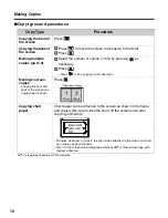
Page 11: ...r to Loading the copy paper When not in use be sure to turn the power off 2 Press the Copy Key Text and illustrations on the screen will be copied and copies emerge from the output port The copied paper holder can hold up to 5 copies Note that exceeding the copied paper holder s capacity may result in paper jams For details on making multiple copies 2 screen copies and so on see page 12 While copy...

Page 12: ...cessary Press Press to stop copying in mid operation Making 2 screen copies Copying the front and back of the screen on a single sheet of paper Press Copying chart paper Chart paper can be attached to the screen as shown in the figure and copied Be sure to take the chart off the screen soon after copying is finished Wrinkles slackness or folds in the chart when attached to the screen will show up ...

Page 13: ...ough the output port about 4 cm 11 2 inches Refer to step 4 on page 10 In case paper cannot go through just put the paper on the paper feed roller and insert the top of the paper in the cutter cover as shown in the figure 5 Close the printer door securely using two hands Use copy paper roll with a core diameter of 25 4 mm 1 inch or more Using a copy paper roll with a smaller core could cause paper...

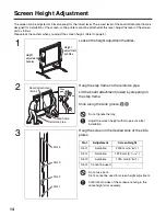
Page 14: ...ment lower by stepping on the step frame Slide along the slide groove Do not handle the tray Adjust the screen height with two persons after installation 3 Hang the screen in the desired slots of the slide plates Do not use slot 4 Slot 4 cannot be used for screen height adjustment Confirm both sides of the screen are hung in the same height slots securely Slot Adjustment Screen Height Slot 1 Avail...

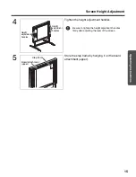
Page 15: ...ht adjustment handles Be sure to tighten the height adjustment handles firmly after adjusting the level of the screen 5 Store the step frame by hanging it on the board attachment upper Height adjustment handles Height adjustment handles Step frame Board attachment upper ...

Page 16: ...asonic DMS software TWAIN driver View Manuals Adobe Acrobat Reader Connecting the unit to a computer Power on the electronic board and connect the unit and your computer with a USB cable Caution Use a shielded USB cable that is certified as logo by USB IF When you connect the unit for the first time install the USB and Printer driver to your computer Windows 98 Page 17 Windows Me Page 18 Windows 2...

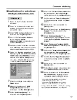
Page 17: ...e best driver for your device Recommended check button and click the Next button 11 Confirm that the Specify a location is the same as step 6 click the Next button 12 When the driver is found click the Next button 13 When the installation of USB Printing Support is completed click the Finish button 14 When Unknown Device is detected again repeat steps 9 to 13 to install Panaboard UB5 USB Device Dr...

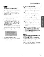
Page 18: ...inish button 8 When Panaboard UB5 USB Printer is detected click on the Specify the location of the driver Advanced check button and click the Next button 9 Confirm that the Specify a location is the same as step 5 click the Next button 10 When the driver is found click the Next button 11 When the installation of USB Printing Support is completed click the Finish button 12 When PanasonicPanaboard U...

Page 19: ...vary depending on your computer To search for the file in your computer 1 Click the Start button on the Task Bar and then click on Find Files or Folders Windows 98 or Search For Files or Folders Windows Me 2 A dialog box appears prompting for a file name to be searched type DRIVER CAB in the Named Windows 98 or Search for files or folders named Windows Me box choose C in the Look in box and check ...

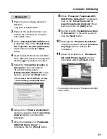
Page 20: ...ton 9 Although Digital Signature Not Found dialog box appears click the Yes button to continue the installation 10 When the installation of Panaboard UB5 USB Device Driver is completed click the Finish button 11 When Welcome to the Found New Hardware Wizard dialog box appears again click the Next button 12 When Unknown is detected click on the Search for a suitable driver for my device recommended...

Page 21: ...CD ROM drive It may cause installing a wrong USB driver 6 Although the Hardware Installation dialog box appears click the Continue Anyway button to continue the installation 7 When the installation of Panaboard UB5 USB Device Driver is completed click the Finish button 8 When Panasonic Panaboard UB5 USB Printer A4 Letter is detected click on the Install from a list or specific location Advanced ch...

Page 22: ...ton 5 Click the Panasonic DMS button Click Adobe Acrobat Reader 5 0 to install the Acrobat Reader To read the operating instructions the Acrobat Reader must be installed in your computer 6 Click the Install Panasonic DMS Software button 7 Enter the installation destination and click the Next button 8 Enter the data folder and click the Next button 9 Select UB 5xxx and click the button Select and a...

Page 23: ...em Document Manager For Windows XP All Programs instead of Programs The Panasonic DMS software runs 2 Click the File menu then click Select Source 3 Select Panaboard UB5 USB TWAIN Driver and click the Select button 4 Click the File menu then click Acquire Image or click the scanner icon on the Toolbar The Panaboard Operation Panel will appear When the Panaboard Operation Panel is not displayed che...

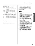
Page 24: ...n This button scans the front and back of the screen on a single page Multi Copy Error Indicator This indicator displays the number of copies to be made The display changes each time the Multi Copy Stop Button is pressed Example 1 2 9 1 When an error occurs a flashing symbol will appear in this display to indicate the error status See page 29 Multi Copy Stop Button When making multiple copies pres...

Page 25: ... and select the printer name set when installing The standard printer name is Panaboard UB5 USB Printer Letter The Multi Copy Error Indicator flashes when printing After printing all the panel keys are disabled until the Multi Copy Error Indicator lights When the operation panel of the TWAIN driver is displayed printing is not available You cannot stop printing after printing starts Do not attempt...

Page 26: ...th a small amount of ethyl alcohol Do not use thinner benzine or cleaners containing abrasives as this may result in discoloration Do not wipe the screen film with a dry cloth as this may generate a static charge Caring for the eraser When the erasing surface of the eraser becomes dirty hold down the sheet under the top sheet with your finger and peel off the dirty sheet by pulling in the directio...

Page 27: ...r feed roller Dampen a soft cloth with neutral kitchen cleaner diluted in water wring the cloth thoroughly and wipe the entire surface of the roller while rotating it If this does not remove all dirt wipe with a cloth dampened with ethyl alcohol 4 Load the copy paper and close the printer door securely using two hands For details on loading the copy paper see page 10 Printer head Gold Cotton swab ...

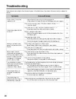
Page 28: ...open Close the printer door firmly using two hands until a click is heard 10 Black streaks or blank unprinted spots appear on the copy copy paper is dirty The printer head or paper feed roller is dirty Open the printer door and clean any dirt off the printer head and paper feed roller 26 27 A black or white horizontal line appears or the page prints in black or blank The unit is in strong sunlight...

Page 29: ...error Connect the USB cable securely 16 Screen The screen will not move Remove any chart paper attached to the screen and slowly move the screen by hand Paper No paper Load the copy paper roll 10 The printer door is not closed securely Close the printer door securely 10 Cut Printer can not cut the paper Open the printer door and clear the jammed paper 13 Scanner Failure The scanner or screen is in...

Page 30: ...nel surfaces 2 Panel advance system Endless scroll type Copying area Height Width 850 mm 1250 mm 2 915 32 4 17 32 Scanning system Image sensors Output Block Printing system Thermal type Copy paper Heat sensitive roll paper Paper thickness 65 m Core diameter 25 4 mm or more Copy paper size Letter Copy density 8 dots mm 203 dots inch Copy colour Black Contrast adjustment Two levels Normal Dark 2 scr...

Page 31: ... BE DONE BY QUALIFIED SERVICE PERSONNEL AFTER INSTALLING THIS OPTION Installation Manual page Assembling the Electronic Board 32 Accessories for assembling 32 Assembly 33 Electronic Board Operations Check 40 Repacking 41 Assembling the Optional Stand UE 608005 42 Accessories 42 Assembly 43 Wall mounting 46 Wall mounting fixture 46 Wall mounting procedure 47 Attaching the wall mounting fixtures 48 ...

Page 32: ...on the wall Part Name Illustration Quantity Remarks Board attachment upper Wall mounting fixture upper Board attachment lower Wall mounting fixture lower Cover upper Cover lower Screws and spacers For screen For printer and screen For cover For screen For screen Screen Page 35 Step 11 Printer Page 37 Step 17 Cover lower Page 39 Step 22 Paper holder Paper holder Wrench Power cord Wall mounting temp...

Page 33: ...ng box Caution When removing the screen unit grasp the side cover on either side of screen Do not grasp the screen film surface as this may scratch it The shipping box cushioning material and other packing material will be necessary if you ever need to repackage the electronic board so do not throw them away Board attachment lower Board attachment upper Copy paper roll Power cord Cover upper Cover...

Page 34: ...he screen unit to the board attachment upper Hold the side covers of the screen unit and hang two hooks of the screen unit on the left side of the board attachment upper Shift the screen unit to the left until it stops Confirm the left hook is inserted into the groove of the board attachment upper When hanging the screen unit set the board attachment frame at the lowest level Be careful not to cat...

Page 35: ...hion behind the screen Caution Touch the screen film surface gently when opening the screen unit 10Extend the screen unit Hang the right hook of the screen unit on the board attachment upper Caution Touch the screen film surface gently when opening the screen unit 11Fix the screen unit Fix the left center and right panels with the screws and spacers supplied To tighten the screws use the supplied ...

Page 36: ...oothly When lifting the board attachment frame be sure to hold the handle in the center of the frame 14Hang the screen in the desired slots of the slide plates and tighten the handles Caution The screen can be adjusted at 4 levels The lowest level of the board attachment frame is designed for the installation of the screen so the printer cannot be attached at that level Use the electronic board at...

Page 37: ...s of the printer unit on the square holes of the board attachment lower Caution When attaching the printer unit make sure the cable is not caught between the metallic frame and the printer unit 17Tighten the screws for the printer unit Use four screws for the optional stand and two screws for the wall mounting Optional stand Wall mounting Stopper screw Screw short See page 42 Board attachment lowe...

Page 38: ...e cover upper Hook the cover with the projections on both sides then cover the top of the board attachment upper 21Store the shipping screws for fixing the screen panels the screw for the folding frame and the wrench in the tool box on the top of the printer unit Folding support screw Folding support Board attachment upper Cover upper Tool box Shipping screws Wrench Folding support screw ...

Page 39: ...oard attachments upper lower while matching the top edges of them Then install the rivets The rear cover and rivets are supplied with the optional stand 26Wipe the screen film surface Soak a soft cloth with water wring well and wipe the screen film surface Caution Do not wipe the screen film surface with paint thinner benzene or cleaners that contain abrasives Doing so may cause discoloration Do n...

Page 40: ...e the accessory marker to draw a large filling the entire copyable area of the screen film surface Copying area refer to the Operating Instructions page 7 Press twice Press lights up and three copies are made Normal operation Three copies are not made Contact the store or dealer from which the unit was purchased The entire readable area is not printed There are strange noises or paper jams during ...

Page 41: ...g box to the lower box Caution When handling the screen unit grasp the side cover on either side of screen Do not grasp the screen film surface as this may scratch it Board attachment lower Board attachment upper Copy paper roll Power cord Cover upper Cover lower Markers Screen unit Manuals CD ROM Printer unit Eraser Paper holder ï ï A B Joint Screws and spacers ...

Page 42: ...t is used for the stopper screw of step 15 on page 37 Before assembly be sure to lock the casters No Part name Illustration Q ty No Part name Illustration Q ty Base pipe 2 Screw 2 Reinforce pipe 1 Height adjustment handle 4 Extension pipe S 1 Nut 4 Extension pipe L not use 1 Cap 2 Side pipe 2 Step frame 1 Slide plate Left 1 Fall preven tion extension leg 4 Slide plate Right 1 Wrench for stand 1 Fi...

Page 43: ...lectronic board Caution Install and always set the fall prevention legs when using the stand When tightening the screws hold the nut with pliers Assembling the stand Assemble the side pipes with the slide sheets facing inside Fall prevention extension legs Caster locks are attached to the back side Slide sheet Side pipe Base pipe Extension pipe S Base pipe Reinforce pipe Slide sheet ...

Page 44: ...e to the stand Details of the procedures are as follows Step A Attach the fixing plate to the board attachment frame Stamp UL Stamp LL Stamp UR Stamp LR Board attachment upper Slide plate right Board attachment lower Slide plate left Step E Step D Step A Step B Step C Step D Step C Step A Slide plate Fixing plate Cap Height adjustment handle Screw Height adjustment handle Fixing plate Side pipe Si...

Page 45: ...he side pipes from the inside Step D Install and secure the height adjustment handles Step E Fix the caps to the side pipes 4 Assemble and install the electronic board Refer to pages 33 to 39 5 Insert and keep the wrench in the holder on the cover lower Board attachment frame Side pipe Side pipe Fixing plate Screw Wrench for stand Cover lower ...

Page 46: ...rtared walls Accidental electric leakage from the wall mounting fixture bolts to metal laths or wire laths can cause heat smoke or a fire I Tools required A minimum of four 4 pieces of appropriate wall support hardware molley toggle etc NOTE THIS HARDWARE MUST BE LOCALLY PROCURED IT IS NOT INCLUDED IN THE PRODUCT Drill and drill bit of correct size for hardware installation Screw driver Both phill...

Page 47: ...for the wall mounting fixtures Holes on the wall mounting fixture are 1 4 in diameter 2 After removing the wall mounting template attach the wall mounting fixtures with the appropriate wall mounting hardware Refer to the section Attaching the wall mounting fixtures page 48 for drilling in the wall and attaching the mounting fixtures Refer to steps 2 to 23 on pages 33 to 39 for attaching the printe...

Page 48: ...all mounting fixture and tighten until the wall mounting fixture is securely fixed to the wall Drill bit Metal or concrete wall Stud plug Insert a stud plug in each hole Wall mounting fixture Bolt Insert each bolt through a hole in the wall mounting fixture and into the hole in the wall beneath so that the arms of the split wing toggle are horizontal For the correct hole size refer to the instruct...

Page 49: ...stallation Manual Attaching to wooden walls Use wood screws sold in stores For the correct hole size refer to the instructions for the particular wood screws used Wall mounting fixture Wood screw Wooden wall ...

Page 50: ...sonic Digital Document Company A Unit of Matsushita Electric Corporation of America Two Panasonic Way Secaucus New Jersey 07094 2002 2003 Panasonic Communications Co Ltd Printed in Japan PJQXB0050ZA K0503M0 ...

Reviews: