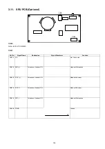

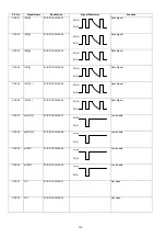
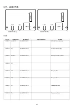
117
CN7-33
+5VP
FCB PCB CN50-33
+5 VDC Power Supply
CN7-34
+24V
FCB PCB CN50-34
+24 VDC Power Supply
CN7-35
GND
FCB PCB CN50-35
Ground
CN7-36
GND
FCB PCB CN50-36
Ground
CN7-37
OPA[3]
FCB PCB CN50-37
Address Signal
CN7-38
OPA[4]
FCB PCB CN50-38
Address Signal
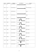
CN7-39
OPA[7]
FCB PCB CN50-39
Address Signal
CN7-40
OPA[8]
FCB PCB CN50-40
Address Signal
CN7-41
OPA[11]
FCB PCB CN50-41
Address Signal
CN7-42
OPA[12]
FCB PCB CN50-42
Address Signal
CN7-43
nCS09
FCB PCB CN50-43
Low Enable
CN7-44
nCS0A
FCB PCB CN50-44
Low Enable
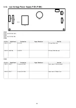
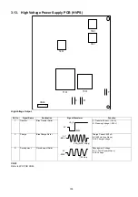
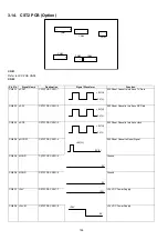
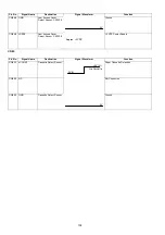
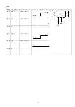
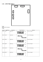
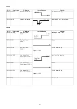
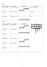
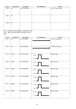
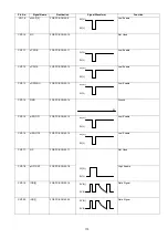
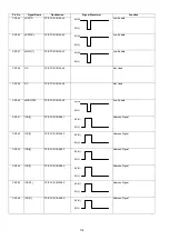
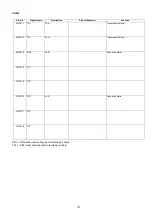
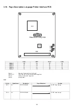
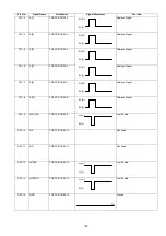
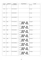
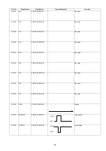
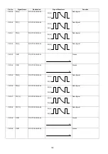
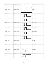
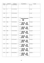
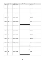
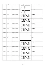
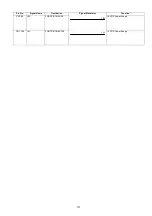
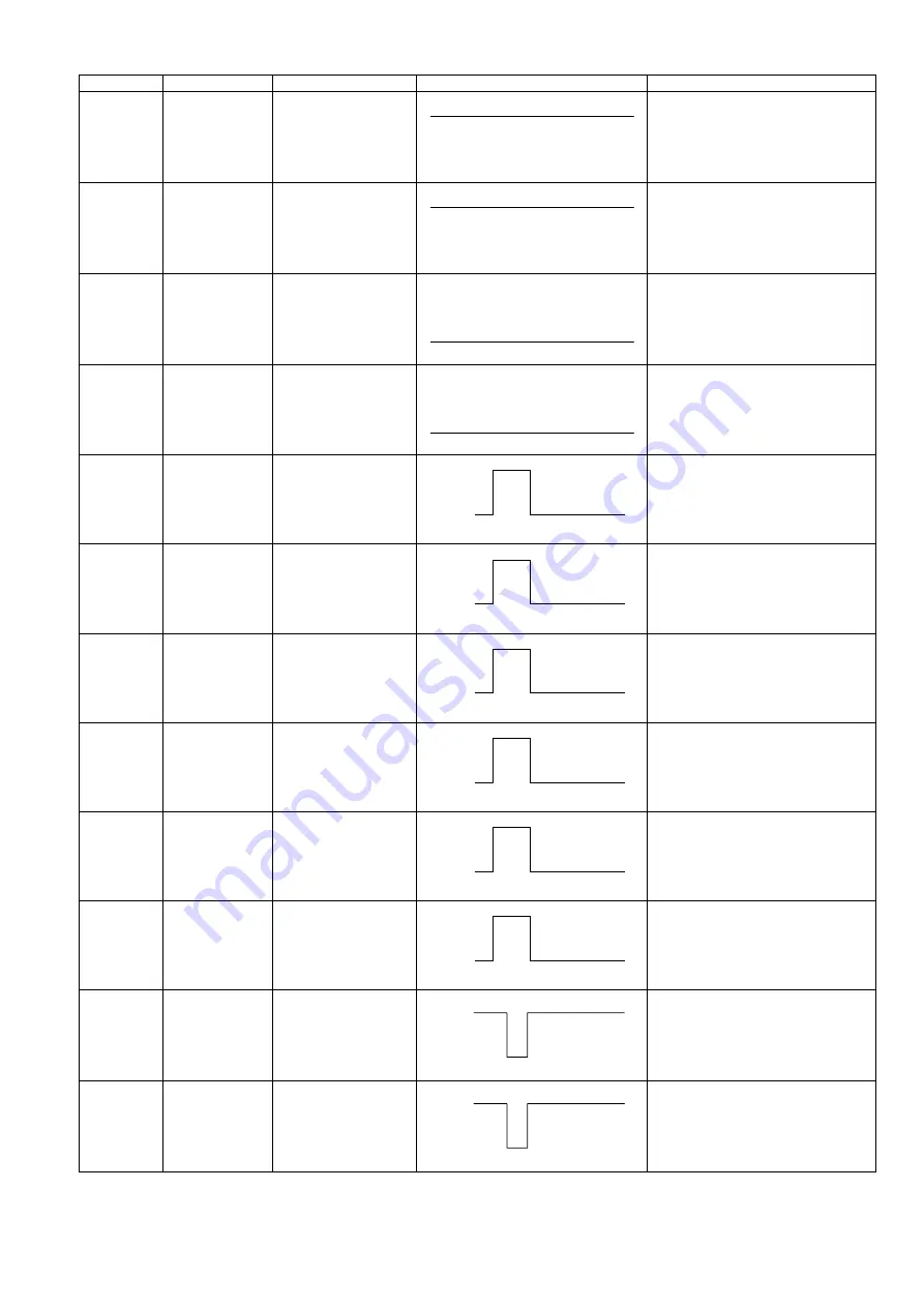
Pin No.
Signal Name
Destination
Signal Waveform
Function
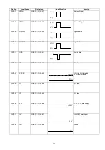
+5V
+24V
0V
0V
5V(H)
0V(L)
5V(H)
0V(L)
5V(H)
0V(L)
5V(H)
0V(L)
5V(H)
0V(L)
5V(H)
0V(L)
3V(H)
0V(L)
3V(H)
0V(L)
Summary of Contents for Panafax DX-2000
Page 2: ......
Page 27: ...27 9 1 Screw 19 10 Release two Latch Hooks 11 Remove the SNS Assembly 121 9 10 11 ...
Page 49: ...49 2 15 Screw Identification Template ...
Page 57: ...57 3 7 3 Option Cassette Circuit 555 748 728 744 928 953 730 731 731 952 944 930 931 931 ...
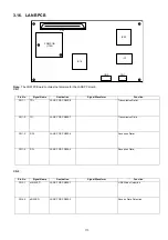
Page 58: ...58 3 7 4 LAN Control Circuit 522 CN50 1102 1104 1101 N C N C RD N C N C RD TD TD ...
Page 59: ...59 3 7 5 Page Description Language Printer Interface Kit ...


