122
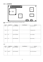
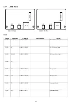
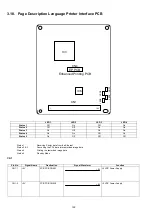
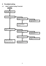
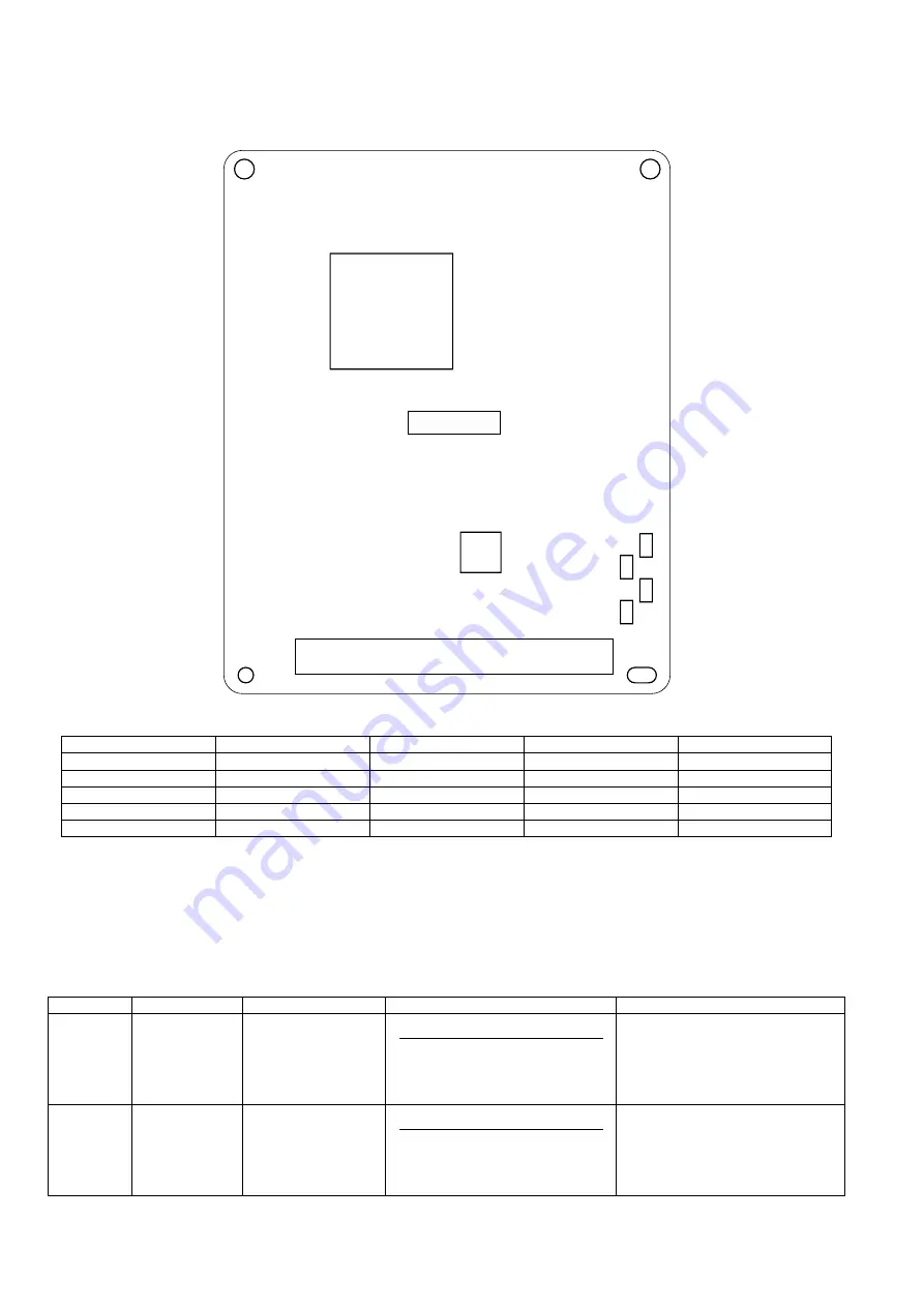
3.18. Page Description Language Printer Interface PCB
CN1
LED 1
LED 2
LED 3
LED 4
Status 1
Off
On
Off
On
Status 2
Off
Off
On
On
Status 3
On
Off
On
On
Status 4
On
On
Off
On
Status 5
On
Off
Off
Off
Status 1
:
Receiving Printer data from the Ethernet
Status 2 & 3
:
Converting the PCL data into rasterized image data
Status 4
:
Printing the rasterized image data
Status 5
:
Standby Mode
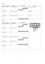
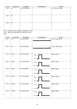
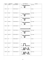
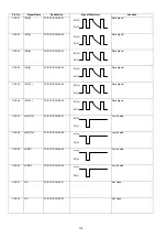
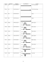
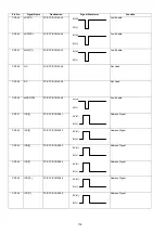
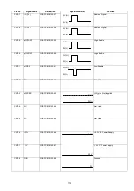
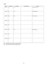
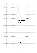
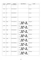
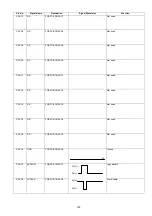
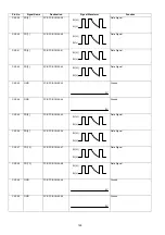
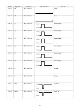
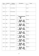
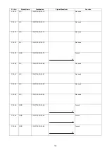
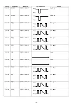
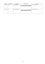
Pin No.
Signal Name
Destination
Signal Waveform
Function
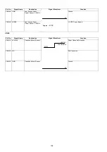
CN1-1
+5V
FCB PCB CN55-1
+5 VDC Power Supply
CN1-2
+5V
FCB PCB CN55-2
+5 VDC Power Supply
CN1
CN4
IC3
IC6
Enhanced Printing PCB
EP PCB
1
100
LED1
LED2
LED3
LED4
+5V
+5V
Summary of Contents for Panafax DX-2000
Page 2: ......
Page 27: ...27 9 1 Screw 19 10 Release two Latch Hooks 11 Remove the SNS Assembly 121 9 10 11 ...
Page 49: ...49 2 15 Screw Identification Template ...
Page 57: ...57 3 7 3 Option Cassette Circuit 555 748 728 744 928 953 730 731 731 952 944 930 931 931 ...
Page 58: ...58 3 7 4 LAN Control Circuit 522 CN50 1102 1104 1101 N C N C RD N C N C RD TD TD ...
Page 59: ...59 3 7 5 Page Description Language Printer Interface Kit ...


