225
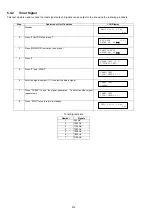
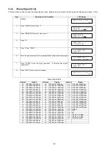
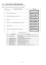
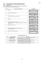
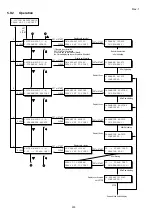
5.8.3
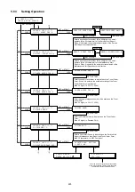
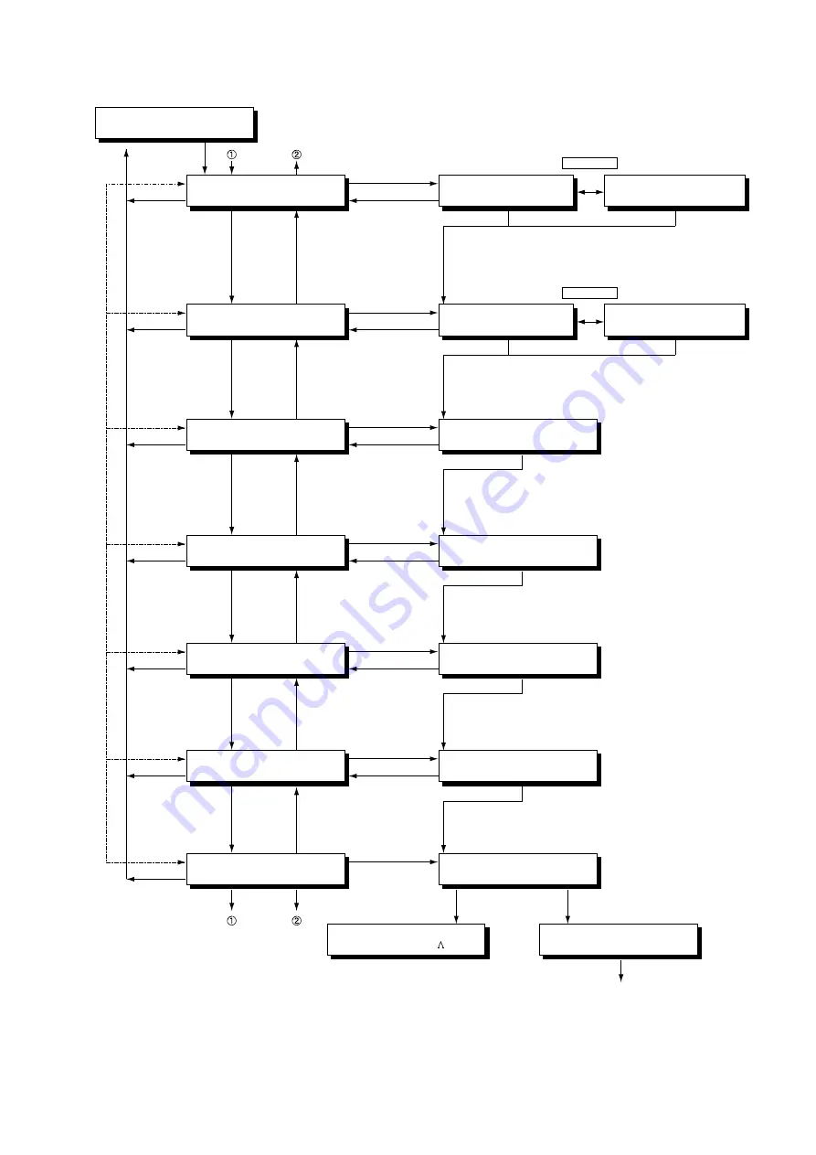
Setting Operation
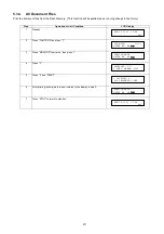
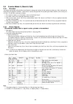
8:CHECK & CALL
PRESS SET TO SELECT
CHECK & CALL (1-7)
1:SVC. ALERT FAX #
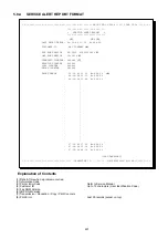
SERVICE ALERT FAX #
SET or START
SET or START
SET or START
INTERNET
CLEAR
CLEAR
Enter a destination fax number (Max. 36 digits) or an email
address (Max. 60 characters) for the Service Alert Report.
When it is entered, the automatic transmission of the Service
Alert Report becomes effective.
CHECK & CALL (1-7)
2:MAINT. ALERT FAX #
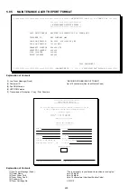
MAINT. ALERT FAX #
SERVICE ALERT MAIL #
MAINT. ALERT MAIL #
SET or START
SET or START
SET or START
SET or START
CLEAR
CLEAR
Enter a destination fax number (Max. 36 digits) or an email
address (Max. 60 characters) for the Maintenance Alert
Report. When it is entered, the automatic transmission of the
Maintenance Alert Report becomes effective.
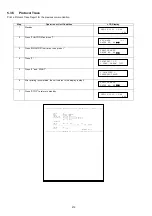
CHECK & CALL (1-7)
3:TONER ORDER FAX #
TONER ORDER FAX #
SET or START
SET or START
CLEAR
CLEAR
Enter the supply fax number to be printed on the Toner Order
Form. When it is entered, the automatic printing of the Toner
Order Form becomes effective.
Max. 36 digits (i.e. 201 111 4444)
CHECK & CALL (1-7)
4:TONER ORDER TEL #
TONER ORDER TEL #
SET or START
SET or START
CLEAR
CLEAR
Enter the supply telephone number to be printed on the Toner
Order Form.
Max. 36 digits (i.e. 201 111 5555)
CHECK & CALL (1-7)
5:DEALER NAME
DEALER NAME
SET or START
SET or START
CLEAR
CLEAR
Enter the Dealer's Name to be printed on the Toner Order
Form.
Max. 25 digits (i.e. Panafax Corp.)
CHECK & CALL (1-7)
6:CUSTOMER ID
CUSTOMER ID
SET or START
SET or START
CLEAR
CLEAR
Enter a Customer ID code to be printed on the Service Alert
Report, Maintenance Alert Report and Toner Order Form.
Max. 16 characters (i.e. ABC Company)
6
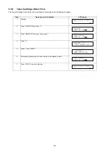
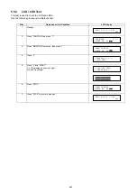
CHECK & CALL (1-7)
7:PRINTER REPORT XMT
PRINTER REP. XMT:Off
1:OFF 2:ON
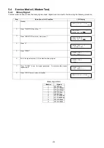
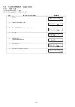
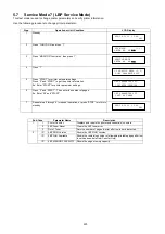
SERVICE MODE
ENTER NO. OR V
* DIALING *
555 1234
SET or START
CLEAR
7
5
4
3
2
1
2
1
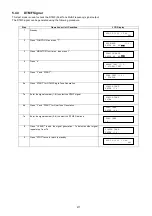
After the Service Alert Report is transmitted
to the pre-registered FAX # or Email Address,
the machine returns to standby mode.
INTERNET
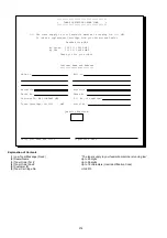
Summary of Contents for Panafax DX-2000
Page 2: ......
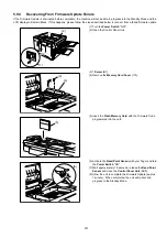
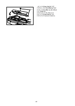
Page 27: ...27 9 1 Screw 19 10 Release two Latch Hooks 11 Remove the SNS Assembly 121 9 10 11 ...
Page 49: ...49 2 15 Screw Identification Template ...
Page 57: ...57 3 7 3 Option Cassette Circuit 555 748 728 744 928 953 730 731 731 952 944 930 931 931 ...
Page 58: ...58 3 7 4 LAN Control Circuit 522 CN50 1102 1104 1101 N C N C RD N C N C RD TD TD ...
Page 59: ...59 3 7 5 Page Description Language Printer Interface Kit ...