
235
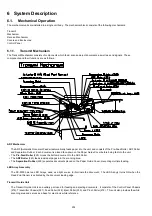
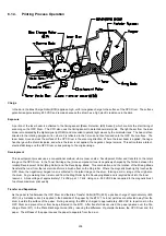
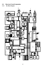
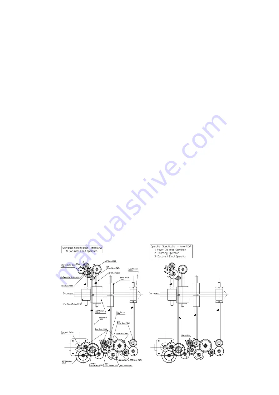
Transmit Mechanism Drive System
This system feeds documents through the transmitting mechanism, and consists of rollers, gears and a stepper motor.
• The Transmit Motor (346), a stepper motor, controlled by the CPU, drives the Pre-Feed Roller, ADF Roller, Feed Roller and
Eject Roller, with the speed based on the density of the picture information.
• The Feed Roller (328) feeds the document to the scanning point.
• The Eject Roller (330) feeds and ejects the document out of the machine.
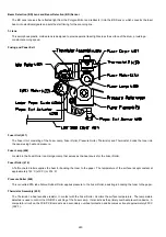
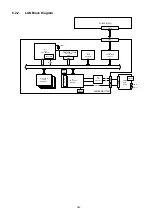
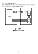
Transmit Mechanism Sensors [SNS PCB (121)]
The SNS Assembly (121) performs two functions. The ADF Sensor (PC3), activated by Actuator A (120), detects the presence
of documents on the ADF Tray and multiple pages. The WID (A4/B4 size document width) Sensor (PC1), activated by Actuator
D (134), detects documents that are wider than 9.1 inches (232 mm). The size of the reproduced copy is reduced when the
receiver is capable of printing only letter and A4 size. The size remains the same when the receiver is capable of printing B4
size copies. Width reduction is also in effect in the copy mode.
The RP (Read Point) Sensor (PC2), activated by Actuator B (119), detects the lead and trail edges of the document, controlling
the reading position. The CPU determines that a document is jammed if Actuator B is not tripped within a specified time after
the ADF Roller starts feeding, and disengages the Pre-Feed and ADF Rollers by reversing the Transmit Motor direction.
The ADF Door Sensor (PC1), activated by Actuator C (118), halts all scanning operations when the Control Panel Unit is open.
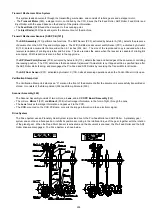
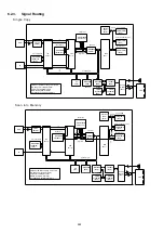
Verification Stamp Unit
The Verification Stamp Unit stamps an “X” mark on the front of the document after the document is successfully transmitted or
stored. It consists of the Stamp Holder (334) and Stamp Solenoid (335).
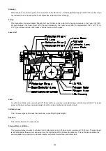
Scanner Assembly (340)
The Scanner Assembly consists of two mirrors, a Lens, and a CCD PC Board Assembly (342).
• The mirrors, Mirror 1 (337) and Mirror 2 (338) reflect image information, in the form of light, through the Lens.
• The Lens focuses the image information and passes it to the CCD.
• The CCD, mounted on the CCD PC Board, converts the image information into an electronic signal.
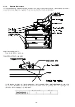
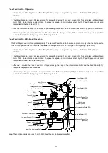
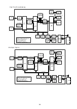
Drive System
The Drive System uses a Planetary Gear System to provide drive to the Pre-Feed Roller and ADF Roller. A planetary gear
system does not have a fixed position; it shifts its position according to the rotational torque of the gear, together with the rotation
of the planet gear. When the Read Point Sensor is activated, and the document is scanned, the Pre-Feed Roller and the ADF
Roller drive are disengaged. The Drive System is shown below.
Summary of Contents for Panafax DX-2000
Page 2: ......
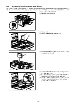
Page 27: ...27 9 1 Screw 19 10 Release two Latch Hooks 11 Remove the SNS Assembly 121 9 10 11 ...
Page 49: ...49 2 15 Screw Identification Template ...
Page 57: ...57 3 7 3 Option Cassette Circuit 555 748 728 744 928 953 730 731 731 952 944 930 931 931 ...
Page 58: ...58 3 7 4 LAN Control Circuit 522 CN50 1102 1104 1101 N C N C RD N C N C RD TD TD ...
Page 59: ...59 3 7 5 Page Description Language Printer Interface Kit ...


